view
views
view
Version of 2 December 2006.
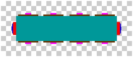
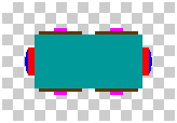
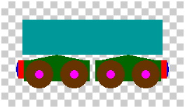
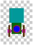
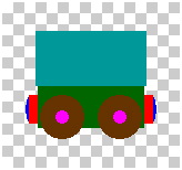
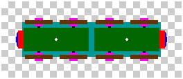
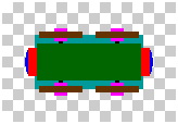
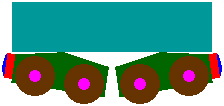
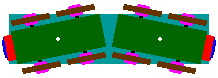
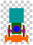
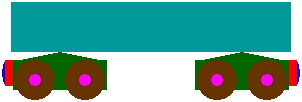
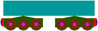
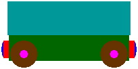
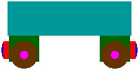
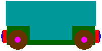
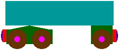
Figure 1 contains scale drawings of two typical toy train cars; they do not represent any one brand exactly. The left-hand column has a four-axle car that is about 110mm long (including couplers), the right-hand has a two-axle car about 60mm long, and the middle column has an end view of either.
| Four axles | Either | Two axles | |
|---|---|---|---|
| Top view | |
| |
| Lateral views | | |
|
| Bottom view | |
| |
| Figure 1 | |||
Each of the gray and white blocks throughout the background is a 5mm square, and the same scale is used throughout this page except where marked otherwise. Colors designate different parts of the cars:
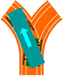
Although a two-axle car is satisfactorily served by one frame, a four-axle car needs to be articulated, having two frames with pivots (represented by white dots in the bottom views) connecting the frames to the body. Figure 2 shows how the frames can move, in response to varying track configurations, with a certain independence from the body.
 | 
|
| Figure 2-a | Figure 2-b |
|---|
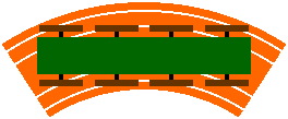
Figure 3 shows, in overhead view and two cross sections, a curved track having a radius (to its centerline) of 100mm, which is the practical minimum for toy trains of this genre. Measuring 40mm wide and 12mm thick, each face of the track consists of:
 |
| Figure 3 |
|---|
Like the cars, this track is merely a typical design, and does not exactly represent any manufacturer's product. However, it does embody the usual feature where grooves are cut into both faces of the track: by allowing asymmetric pieces to be flipped over, there is no need to manufacture both a piece and its mirror image.
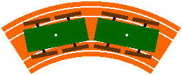
Figure 4 illustrates how a car fits onto this track.
 |
| Figure 4 |
|---|
Figure 5-a reveals one reason why four-axle cars need articulated frames. In a rigid design, some of the wheels will not fit into the track groove, no matter where the car is placed. Figure 5-b shows how the pivots correct the problem.
 | 
|
| Figure 5-a unacceptable | Figure 5-b acceptable |
When an car with an articulated frame heads into a switch (figure 5-c), there is a risk that the two member frames might go different directions. This is shown in figures 5-d (with car body) and 5-e (without), where a train car is moving from bottom to top. The front frame (marked 'F') turns to the left, but the rear frame ('R') wanders toward the right. In practice, this problem is virtually eliminated by limiting the horizontal angle through which a frame may rotate, relative to the car body, to roughly 10°. An alternate remedy is to use a switch that has moving parts to guide the wheels.
 |  | 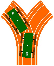
|
| Figure 5-c | Figure 5-d unacceptable | Figure 5-e unacceptable |
The overhead view of figure 5-b or 5-e might suggest that the entire diameter of the wheel must fit into the groove on a curve, yet this is not the case. Figure 6 clarifies the matter. If the groove is 3mm deep, only the bottom 3mm of the wheel (bright green) need fit into it. On a sharp curve, certain portions (bright cyan) might without harm hang over the curb or median; this is more likely to happen if wheels are of larger diameter. Figure 6-a has the usual wheel of 20mm diameter encountered in the examples so far. Figure 6-b in contrast shows a 30mm wheel, which is sometimes found on locomotives.

|
| Figure 6-a scale 2x |

|
| Figure 6-b scale 2x |
A second reason for articulating the frame is to manage vertical curvature. The ascender in figure 7, sectioned through the grooved portion of the track, rises 60mm through a horizontal distance of 200mm. Although steep, this is representative of toy train track as actually sold. Figure 7-a shows what can go wrong without articulation: half the wheels fail to touch the track, and the magnetic couplers nearly lose contact with each other. Figure 7-b shows how articulation corrects the problem; arguably better is to use ascenders with slope changes of less severity.
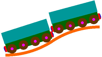 |
| Figure 7-a unacceptable |
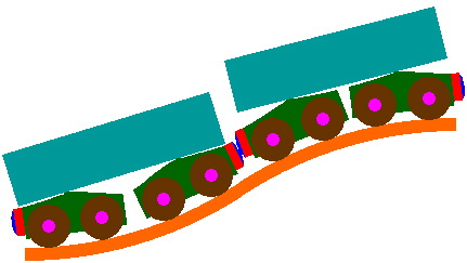 |
| Figure 7-b acceptable |
Not pictured thus far is a three-axle rigid frame, which is possible but requires careful planning so that the wheels do not become stuck in curves and switches. Certain factors will ease design:
The long cars in figure 8 have little hope of negotiating a curve of 100mm radius, but should have no problem with 200mm.
 |
| Figure 8-a |
|---|
 |
| Figure 8-b |
Figure 9 shows that the frame of a two-axle car might or might not extend the entire length of the car. Figure 9-c shows a modification that allows taller cargo to be carried.
 |  | 
|
| Figure 9-a | Figure 9-b | Figure 9-c |
|---|
Figure 10 depicts an asymmetric car, with two axles at one end and one axle at the other.
 |
| Figure 10 |
|---|
An articulated body is featured in the very long car of figure 11-a; the gaps between body segments could be enclosed with a flexible pleated material, as in figure 11-b.
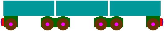 |
| Figure 11-a |
|---|
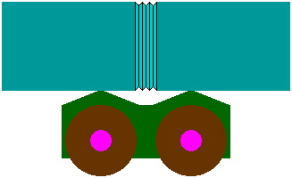 |
| Figure 11-b scale 2x |
This multi-section car incurs the same risk of misswitching as illustrated in figure 5-d.