 | 
|
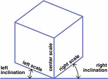
| the general case | an example |
|---|
|
|
| the general case | an example |
|---|
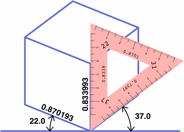
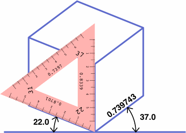
Not corresponding to any obvious feature of the drawing is the center inclination, which is defined as 90° minus the sum of the left and right inclinations. In this example, the center inclination is 90° − (22° + 37°) = 31°. Introduction of the center inclination, an admittedly arbitrary quantity, simplifies later explanations and formulas.
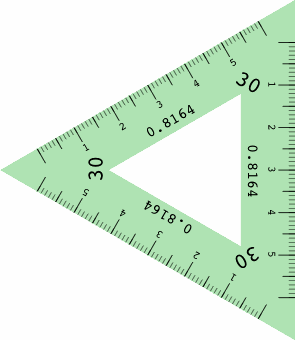
If all three of the inclinations are different, the projection is traditionally termed trimetric, if two are equal dimetric (often misspelled "diametric"), and if all are equal isometric (although "monometric" would be a more consistently formed adjective). The calculator handles any of these without distinction.
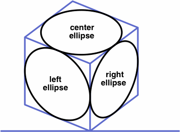
Besides scales or inclinations, each of the top and bottom parts of the calculator gives projection angles for ellipses derived from circles drawn on the three principal planes, as illustrated below. The closer the projection angle is to 90°, the closer the ellipse is to a circle. These numbers aid in selecting ellipse templates, which are manufactured for technical drawing and are labeled with the projection angle.
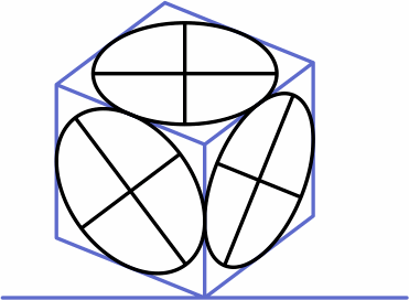
The major axis of each ellipse is drawn to 100% scale. The minor axis, which is shorter, happens to be drawn parallel to the direction in which one of the principal axes is drawn. Note that the ellipse's axes do not necessarily align with the diagonals of the quadrilateral in which it resides.
| 
|
Each of the scale outputs will be between 0 and 1, and the sum of their squares will be 2. Thus the squares of the scales obey the triangle inequality. The squares of any successful trio of scale ratios will also satisfy the triangle inequality.
The JavaScript used here displays NaN for combinations of input numbers that do not yield a legitimate axonometric projection.
When three angles sum to 90 degrees, the axonometric projections derived from using any two of them as left and right inclinations will yield the same numbers, rearranged, for the scales and ellipse projections. For example, 22° + 37° + 31° = 90°, hence the following table which contains many repeated numbers:
| inclinations | scales | ellipse projections | |||||
|---|---|---|---|---|---|---|---|
| left | right | left | center | right | left | center | right |
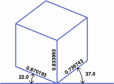
| 22.0° | 37.0° | 0.870193 | 0.833993 | 0.739743 | 42.290510° | 33.488868° | 29.518878° |
| 37.0° | 31.0° | 0.833993 | 0.739743 | 0.870193 | 29.518878° | 42.290510° | 33.488868° |
| 31.0° | 22.0° | 0.739743 | 0.870193 | 0.833993 | 33.488868° | 29.518878° | 42.290510° |
| 37.0° | 22.0° | 0.739743 | 0.833993 | 0.870193 | 29.518878° | 33.488868° | 42.290510° |
| 31.0° | 37.0° | 0.870193 | 0.739743 | 0.833993 | 33.488868° | 42.290510° | 29.518878° |
| 22.0° | 31.0° | 0.833993 | 0.870193 | 0.739743 | 42.290510° | 29.518878° | 33.488868° |
In the table above, the inclinations are integers. For the scales, integers are not possible in nondegenerate cases, but exact thousandths are possible, as in the next table:
| inclinations | scales | ellipse projections | |||||
|---|---|---|---|---|---|---|---|
| left | right | left | center | right | left | center | right |
| 6.562524° | 7.886669° | 0.744 | 0.992 | 0.680 | 47.156356° | 7.252247° | 41.926723° |
| 7.886669° | 75.550807° | 0.992 | 0.680 | 0.744 | 41.926723° | 47.156356° | 7.252247° |
| 75.550807° | 6.562524° | 0.680 | 0.744 | 0.992 | 7.252247° | 41.926723° | 47.156356° |
| 7.886669° | 6.562524° | 0.680 | 0.992 | 0.744 | 41.926723° | 7.252247° | 47.156356° |
| 75.550807° | 7.886669° | 0.744 | 0.680 | 0.992 | 7.252247° | 47.156356° | 41.926723° |
| 6.562524° | 75.550807° | 0.992 | 0.744 | 0.680 | 47.156356° | 41.926723° | 7.252247° |
On the other hand, it is difficult to find a trio of ellipse projection angles all of which can be written as terminating decimals.
To write the conversion formulas explicitly, it helps to first define some variables:
| LI, CI, RI: | left, center, right inclinations |
| LS, CS, RS: | left, center, right scales |
| LR, CR, RR: | left, center, right scale ratios |
| LE, CE, RE: | left, center, right ellipse projection angles |
| others: | intermediate variables |
The following sequence, where LI and RI are the inputs, converts inclinations to scales:
| CI | = | 90° − ( LI + RI ) |
| LT | = | tan ( LI ) |
| CT | = | tan ( CI ) |
| RT | = | tan ( RI ) |
| LS | = | √ ( 1 − CT × LT ) |
| CS | = | √ ( 1 − LT × RT ) |
| RS | = | √ ( 1 − RT × CT ) |
The next sequence, where LR, CR and RR are the inputs, converts scale ratios to inclinations:
| DR | = | √ ( 0.5 × ( LR × LR + CR × CR + RR × RR ) ) |
| LS | = | LR ÷ DR |
| CS | = | CR ÷ DR |
| RS | = | RR ÷ DR |
| LU | = | 1 − LS × LS |
| CU | = | 1 − CS × CS |
| RU | = | 1 − RS × RS |
| LI | = | atan ( √ ( LU × CU ÷ RU ) ) |
| CI | = | atan ( √ ( RU × LU ÷ CU ) ) |
| RI | = | atan ( √ ( CU × RU ÷ LU ) ) |
Either way, these formulas follow:
| LE | = | acos ( RS ) |
| CE | = | acos ( CS ) |
| RE | = | acos ( LS ) |
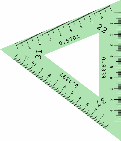
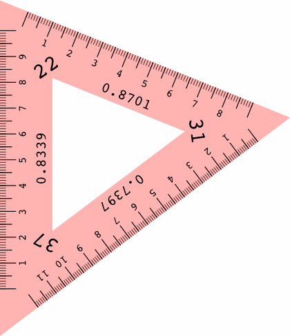
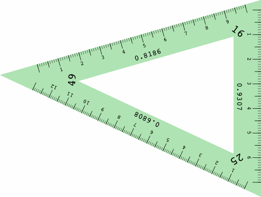
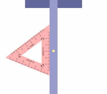
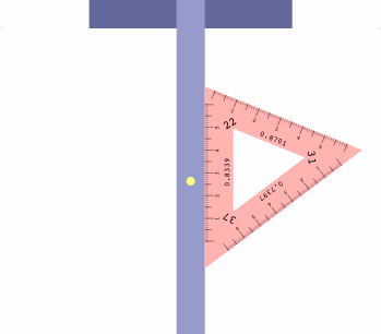
There is a particular type of drafting triangle, not currently manufactured, that can aid in axonometric drawing. An example is shown below, its front and back being mirror images of each other except for the direction that the numbers are printed. The triangle is made opaque for easier reading, and the two sides are different colors to reduce human error.
 | 
|
Essential is the ruler on each edge, scaled to correctly measure distances in that direction, and labeled with the foreshortening ratio.
 | 
|
For the most part, different triangles are required for different projections, but a collection of five or so triangles would satisfy many purposes. Helping to reduce cost is the simple design with no moving parts.
The next illustrations show how the angles of the triangle relate to lines drawn parallel to the principal axes:
 | 
|
These triangles are used with a t-square oriented not horizontally, as is usual, but instead vertically — because in conventional axonometric drawing, one axis is drawn vertically. Some drafting machines use a sliding vertical bar which might be adapted to the purpose.
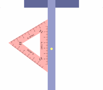
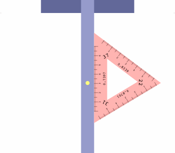
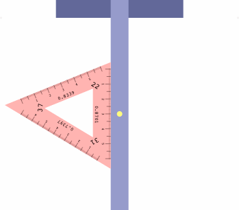
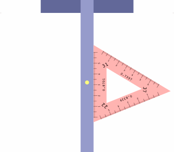
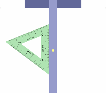
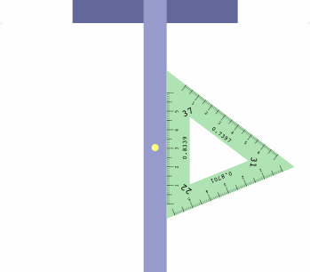
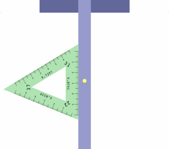
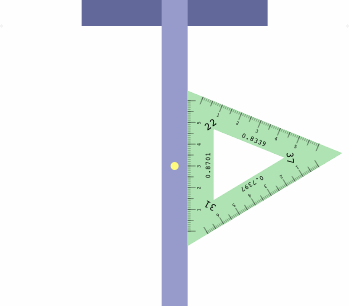
The table below shows how to obtain six projections with one triangle, which may be placed on either side of the t-square as convenient.
| LI = 22 RI = 37 | LI = 37 RI = 31 | LI = 31 RI = 22 |
|---|---|---|
|  
|  
|
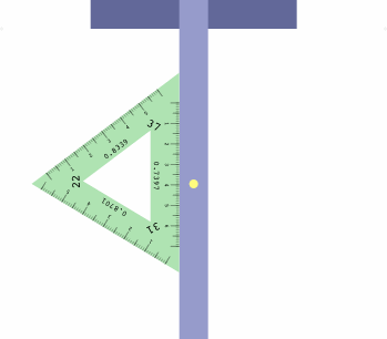
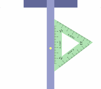
| LI = 37 RI = 22 | LI = 31 RI = 37 | LI = 22 RI = 31 |
|---|---|---|
|  
|  
|
There is a method to assist in getting the triangle correctly oriented. Imagine a diminutive observer standing on the t-square at the yellow dot, and facing the triangle. If all is correct, the left inclination will appear on the observer's left, the right inclination on the right, and the center inclination will be ahead.
Of great interest is Alfred Chandronnait's United States Patent 3711953 for a mechanical apparatus that aids in drawing axonometric projections. Supplied with a variety of rulers in different scales, it employs arms that adjust to desired angles and hold selected rulers. It also includes a sliding device that indicates what settings to choose.
The figures were prepared with Adobe PostScript, still the standard for programmers who need unremittingly precise computer graphics. Some preliminary calculations were done in C++.