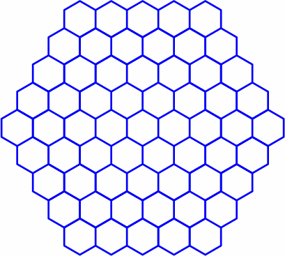
§1. The tessellation of regular hexagons on a plane has been known for centuries. Here is an example:

|
| — figure 1A — |
|---|
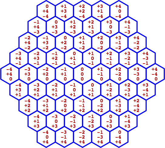
It is often helpful to establish a coördinate system so that each hexagon has a distinct identifier. Of course there is no end of possibilities, but one approach is the zero-sum integer (more briefly "zsi") scheme — all components are integers, and their sum is zero. This plan is redundant because it uses three numbers to identify regions on a plane, which is only two-dimensional. Nonetheless, the redundancy allows zsis to fully capture the symmetry of the configuration; a side benefit is that it sometimes discloses mistakes in calculation. Here is a typical layout, with a ceiling of 4:
|
| — figure 1B — |
|---|
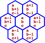
The relation between adjacent hexagons is:
|
| — figure 1C — |
|---|
When rendering zsis in text, we write the three numbers between double square brackets; a mnemonic for this is "redundant brackets for redundant coördinates". For instance, in figure 1B the hexagon at the upper left is notated [[ 0, +3, −3 ]], and the hexagon at the center is [[ 0, 0, 0 ]]. In figure 1C, the upper-left hexagon is written [[ a, b + 1, c − 1 ]].
When Cartesian coördinates (more briefly "carts") are employed later, their components will be written between single square brackets to distinguish them from zsis; an example is [ +3.243, 0, −14.38 ]. Our carts will frequently contain non-integers and have non-zero sums.
Strictly speaking, a single number would suffice to label the hexagons, even if the entire infinite plane were tiled with hexagons that are, like ours, neither infinite nor infinitesimal (see denumerable). Not apparent, however, is any single-number plan that does not entail cumbersomeness of calculations.
§2. For zsis the definitions of addition and subtraction are unsurprising:
[[ a0, a1, a2 ]] + [[ b0, b1, b2 ]] = [[ a0 + b0, a1 + b1, a2 + b2 ]]
[[ a0, a1, a2 ]] − [[ b0, b1, b2 ]] = [[ a0 − b0, a1 − b1, a2 − b2 ]]
Multiplication by an integer is as expected:
n [[ a0, a1, a2 ]] = [[ na0, na1, na2 ]]
Negation is the same as multiplying by −1:
− [[ a0, a1, a2 ]] = [[ −a0, −a1, −a2 ]]
Thus the zsis constitute a vector space.
The magnitude of a zsi ("zsi_mag") is the sum of its positive components, so for instance the zsi_mag of [[ +4, −9, +5 ]] is 9. In other words, the zsi_mag is half the sum of the absolute values of all the components.
A unit zsi is any zsi whose zsi_mag is unity. Later will be introduced zsis with many components, but a unit zsi is always easy to detect because within it exactly one component equals +1, exactly one component equals −1, and all the rest equal zero. This gives rise to a concise notation for unit zsis, consisting of the letter U followed by two single-digit subscripts, the first being the position of +1, and the second being the position of −1. For example, in a context where zsis have three components, U21 equals [[ 0, −1, +1 ]]. Exchanging the subscripts negates the zsi.
A zsi whose magnitude equals n can be written as the sum of precisely n unit zsis. For instance, [[ +3, −4, +1 ]] = 3 U01 + U21. With at least four components, non-unique decomposition is possible: [[ +1, +1, −1, −1 ]] = U02 + U13 = U03 + U12.
The distance between two zsis is by definition the zsi_mag of their difference, as figured by subtraction. When the distance equals one, we term the zsis adjacent.
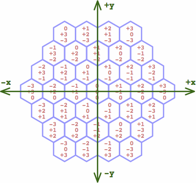
§3. Beneficial is to lay a Cartesian coördinate system over the zsi system. It makes sense to put the origin at the center of hexagon [[ 0, 0, 0 ]]:
|
| — figure 3 — |
|---|
An attractive pair of conversion formulas from a zsi [[ z0, z1, z2 ]] to a cart [ x0, x1 ] is:
| x0 = ( z0 − z1 ) × 0.5
x1 = − z2 × √ 0.75 |
We retain, for calculating the magnitude of a cart ("cart_mag"), the traditional Euclidean square root of the sum of the squares: √ ( x02 + x12 ). Note that the zsi_mag generally does not equal the corresponding cart_mag, but equality does occur when the zsi_mag equals unity, and this case is important for what comes later.
§4a. In a slight shift of interpretation, we now regard a zsi as representing not an entire hexagon, but instead the point at its center. Retaining the zsi-to-cart conversion formulae from above, the centers of the unit-zsi hexagons form a larger regular hexagon:
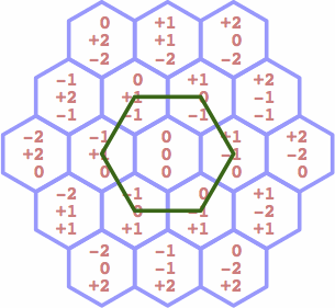
|
| — figure 4A — |
|---|
This leads to the first step of multi-dimensional generalization:
The desired polytope is, more specifically, the convex hull of its vertices. This sequence of these polytopes, one for each dimensionality, constitutes the generalization of regular hexagons mentioned in the title of this article. The polytopes need names, and we write G2 for the ordinary hexagon above, using "G" for general and "2" for two-dimensional. Then G3 is three-dimensional, et cetera. Note that the carts for the vertices of Gn have n components, but the corresponding zsis have n + 1 components.
§4b. The second step involves calculating the cart for each zsi. Recall the two-dimensional case, where the centers of three adjacent hexagons form a regular triangle the length of whose side is unity. This suggests a method for establishing carts in more dimensions.
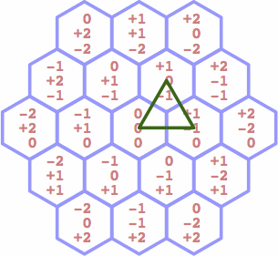
|
| — figure 4B — |
|---|
In the three-dimensional case, we select four adjacent zsis, such as
| [[ | 0, | 0, | 0, | 0 ]] |
| [[ | +1, | −1, | 0, | 0 ]] |
| [[ | +1, | 0, | −1, | 0 ]] |
| [[ | +1, | 0, | 0, | −1 ]] |
and we match them to the vertices of a regular tetrahedron. In n dimensions we match n + 1 adjacent zsis to the n + 1 vertices of a regular simplex.
What follows is a detailed example of one way to do this, mapping 7-component zsi coördinates into 6-component cartesian coördinates in order to build G6. From this procedure the steps for other dimensionalities can be inferred. Writing the generic derivation procedure for the n-dimensional case is cumbersome, but at least the result is easy to generalize.
Elsewhere are given examples of cartesian coördinates for simplices of several dimensions. Relying on that source we begin by defining some constants:
| k0 = 1 ÷ √ ( 2 × 2 ) ≈ 0.50000 |
| k1 = 1 ÷ √ ( 3 × 4 ) ≈ 0.28868 |
| k2 = 1 ÷ √ ( 4 × 6 ) ≈ 0.20412 |
| k3 = 1 ÷ √ ( 5 × 8 ) ≈ 0.15811 |
| k4 = 1 ÷ √ ( 6 × 10 ) ≈ 0.12910 |
| k5 = 1 ÷ √ ( 7 × 12 ) ≈ 0.10911 |
| kn = 1 ÷ √ ( ( n + 2 ) × ( 2n + 2 ) ) |
There exists a six-dimensional simplex, with unit edge length, the carts of whose vertices can be written as:
| [ | 0, | 0, | 0, | 0, | 0, | 0 | ] |
| [ | 2k0, | 0, | 0, | 0, | 0, | 0 | ] |
| [ | k0, | 3k1, | 0, | 0, | 0, | 0 | ] |
| [ | k0, | k1, | 4k2, | 0, | 0, | 0 | ] |
| [ | k0, | k1, | k2, | 5k3, | 0, | 0 | ] |
| [ | k0, | k1, | k2, | k3, | 6k4, | 0 | ] |
| [ | k0, | k1, | k2, | k3, | k4, | 7k5 | ] |
Now we attach some zsis to the carts in an arbitrary manner that will turn out to give good results; the double arrow means "converts to":
| in general: | ||||||||||||||||
| [[ | z0, | z1, | z2, | z3, | z4, | z5, | z6 ]] | ⇔ | [ | x0, | x1, | x2, | x3, | x4, | x5 | ] |
| in particular: | ||||||||||||||||
| [[ | 0, | 0, | 0, | 0, | 0, | 0, | 0 ]] | ⇔ | [ | 0, | 0, | 0, | 0, | 0, | 0 | ] |
| [[ | +1, | −1, | 0, | 0, | 0, | 0, | 0 ]] | ⇔ | [ | 2k0, | 0, | 0, | 0, | 0, | 0 | ] |
| [[ | +1, | 0, | −1, | 0, | 0, | 0, | 0 ]] | ⇔ | [ | k0, | 3k1, | 0, | 0, | 0, | 0 | ] |
| [[ | +1, | 0, | 0, | −1, | 0, | 0, | 0 ]] | ⇔ | [ | k0, | k1, | 4k2, | 0, | 0, | 0 | ] |
| [[ | +1, | 0, | 0, | 0, | −1, | 0, | 0 ]] | ⇔ | [ | k0, | k1, | k2, | 5k3, | 0, | 0 | ] |
| [[ | +1, | 0, | 0, | 0, | 0, | −1, | 0 ]] | ⇔ | [ | k0, | k1, | k2, | k3, | 6k4, | 0 | ] |
| [[ | +1, | 0, | 0, | 0, | 0, | 0, | −1 ]] | ⇔ | [ | k0, | k1, | k2, | k3, | k4, | 7k5 | ] |
Algebraic manipulation yields these conversion formulae:
| x0 = ( z0 − z1 ) k0 |
| x1 = ( z0 + z1 − 2z2 ) k1 |
| x2 = ( z0 + z1 + z2 − 3z3 ) k2 |
| x3 = ( z0 + z1 + z2 + z3 − 4z4 ) k3 |
| x4 = ( z0 + z1 + z2 + z3 + z4 − 5z5 ) k4 |
| x5 = −7 z6 k5 |
Results for other dimensionalities reveal a clear pattern in the table below. In the zsi-to-cart transformation, each x value can feasibly be figured directly from the z values. On the other hand, in the cart-to-zsi transformation, it is practically necessary to figure the z values sequentially.
| zsi ⇔ cart | note the abbreviation yn = xn ÷ kn | ||
|---|---|---|---|
| zsi ⇒ cart | cart ⇒ zsi | ||
| G1 | [[ z0, z1 ]] ⇔ [ x0 ] | y0 = − 2 z1 | z1 = − y0 ÷ 2
z0 = − z1 |
| G2 | [[ z0, z1, z2 ]] ⇔ [ x0, x1 ] | y0 = z0 − z1
y1 = − 3 z2 | z2 = − y1 ÷ 3
z1 = − ( z2 + y0 ) ÷ 2 z0 = − z2 − z1 |
| G3 | [[ z0, z1, z2, z3 ]] ⇔ [ x0, x1, x2 ] | y0 = z0 − z1
y1 = z0 + z1 − 2z2 y2 = − 4 z3 | z3 = − y2 ÷ 4
z2 = − ( z3 + y1 ) ÷ 3 z1 = − ( z3 + z2 + y0 ) ÷ 2 z0 = − z3 − z2 − z1 |
| G4 | [[ z0, z1, z2, z3, z4 ]] ⇔ [ x0, x1, x2, x3 ] | y0 = z0 − z1
y1 = z0 + z1 − 2z2 y2 = z0 + z1 + z2 − 3z3 y3 = − 5 z4 | z4 = − y3 ÷ 5
z3 = − ( z4 + y2 ) ÷ 4 z2 = − ( z4 + z3 + y1 ) ÷ 3 z1 = − ( z4 + z3 + z2 + y0 ) ÷ 2 z0 = − z4 − z3 − z2 − z1 |
| G5 | [[ z0, z1, z2, z3, z4, z5 ]] ⇔ [ x0, x1, x2, x3, x4 ] | y0 = z0 − z1
y1 = z0 + z1 − 2z2 y2 = z0 + z1 + z2 − 3z3 y3 = z0 + z1 + z2 + z3 − 4z4 y4 = − 6 z5 | z5 = − y4 ÷ 6
z4 = − ( z5 + y3 ) ÷ 5 z3 = − ( z5 + z4 + y2 ) ÷ 4 z2 = − ( z5 + z4 + z3 + y1 ) ÷ 3 z1 = − ( z5 + z4 + z3 + z2 + y0 ) ÷ 2 z0 = − z5 − z4 − z3 − z2 − z1 |
| Gn | [[ z0, z1, z2, z3 … zn ]] ⇔ [ x0, x1, x2 … xn−1 ] | y0 = z0 − z1
y1 = z0 + z1 − 2z2 y2 = z0 + z1 + z2 − 3z3 … yn−1 = − (n + 1) zn | zn = − yn−1 ÷ (n + 1)
zn−1 = − ( zn + yn−2 ) ÷ n zn−2 = − ( zn + zn−1 + yn−3 ) ÷ (n − 1) zn−3 = − ( zn + zn−1 + zn−2 + yn−4 ) ÷ (n − 2) … z0 = − zn − zn−1 − zn−2 − … − z1 |
For specialized purposes, rotating the cartesian space might yield numbers or formulas that are more convenient. Another option is to embed the space in a space of higher dimensionality by suffixing any desired quantity of zeroes to the zsis and carts; the formulae were designed to facilitate this. Such is one reason for the large number of negative signs.
To finish the derivation, we list all 42 vertices of G6. To save space, they are written as 21 positive-negative pairs:
| ± [[ | +1, | −1, | 0, | 0, | 0, | 0, | 0 | ]] ⇔ | ± [ | 2k0, | 0, | 0, | 0, | 0, | 0 | ] |
| ± [[ | +1, | 0, | −1, | 0, | 0, | 0, | 0 | ]] ⇔ | ± [ | k0, | 3k1, | 0, | 0, | 0, | 0 | ] |
| ± [[ | 0, | +1, | −1, | 0, | 0, | 0, | 0 | ]] ⇔ | ± [ | −k0, | 3k1, | 0, | 0, | 0, | 0 | ] |
| ± [[ | +1, | 0, | 0, | −1, | 0, | 0, | 0 | ]] ⇔ | ± [ | k0, | k1, | 4k2, | 0, | 0, | 0 | ] |
| ± [[ | 0, | +1, | 0, | −1, | 0, | 0, | 0 | ]] ⇔ | ± [ | −k0, | k1, | 4k2, | 0, | 0, | 0 | ] |
| ± [[ | 0, | 0, | +1, | −1, | 0, | 0, | 0 | ]] ⇔ | ± [ | 0, | −2k1, | 4k2, | 0, | 0, | 0 | ] |
| ± [[ | +1, | 0, | 0, | 0, | −1, | 0, | 0 | ]] ⇔ | ± [ | k0, | k1, | k2, | 5k3, | 0, | 0 | ] |
| ± [[ | 0, | +1, | 0, | 0, | −1, | 0, | 0 | ]] ⇔ | ± [ | −k0, | k1, | k2, | 5k3, | 0, | 0 | ] |
| ± [[ | 0, | 0, | +1, | 0, | −1, | 0, | 0 | ]] ⇔ | ± [ | 0, | −2k1, | k2, | 5k3, | 0, | 0 | ] |
| ± [[ | 0, | 0, | 0, | +1, | −1, | 0, | 0 | ]] ⇔ | ± [ | 0, | 0, | −3k2, | 5k3, | 0, | 0 | ] |
| ± [[ | +1, | 0, | 0, | 0, | 0, | −1, | 0 | ]] ⇔ | ± [ | k0, | k1, | k2, | k3, | 6k4, | 0 | ] |
| ± [[ | 0, | +1, | 0, | 0, | 0, | −1, | 0 | ]] ⇔ | ± [ | −k0, | k1, | k2, | k3, | 6k4, | 0 | ] |
| ± [[ | 0, | 0, | +1, | 0, | 0, | −1, | 0 | ]] ⇔ | ± [ | 0, | −2k1, | k2, | k3, | 6k4, | 0 | ] |
| ± [[ | 0, | 0, | 0, | +1, | 0, | −1, | 0 | ]] ⇔ | ± [ | 0, | 0, | −3k2, | k3, | 6k4, | 0 | ] |
| ± [[ | 0, | 0, | 0, | 0, | +1, | −1, | 0 | ]] ⇔ | ± [ | 0, | 0, | 0, | −4k3, | 6k4, | 0 | ] |
| ± [[ | +1, | 0, | 0, | 0, | 0, | 0, | −1 | ]] ⇔ | ± [ | k0, | k1, | k2, | k3, | k4, | 7k5 | ] |
| ± [[ | 0, | +1, | 0, | 0, | 0, | 0, | −1 | ]] ⇔ | ± [ | −k0, | k1, | k2, | k3, | k4, | 7k5 | ] |
| ± [[ | 0, | 0, | +1, | 0, | 0, | 0, | −1 | ]] ⇔ | ± [ | 0, | −2k1, | k2, | k3, | k4, | 7k5 | ] |
| ± [[ | 0, | 0, | 0, | +1, | 0, | 0, | −1 | ]] ⇔ | ± [ | 0, | 0, | −3k2, | k3, | k4, | 7k5 | ] |
| ± [[ | 0, | 0, | 0, | 0, | +1, | 0, | −1 | ]] ⇔ | ± [ | 0, | 0, | 0, | −4k3, | k4, | 7k5 | ] |
| ± [[ | 0, | 0, | 0, | 0, | 0, | +1, | −1 | ]] ⇔ | ± [ | 0, | 0, | 0, | 0, | −5k4, | 7k5 | ] |
§4c. The unit-zsi coördinates for some other dimensionalities appear in a lengthy listing, from which the following sequence is extracted:
| [[ | +1, | −1 | ]] | ⇔ | [ | 2k0 | ] | ||||||||||
| [[ | +1, | −1, | 0 | ]] | ⇔ | [ | 2k0, | 0 | ] | ||||||||
| [[ | +1, | −1, | 0, | 0 | ]] | ⇔ | [ | 2k0, | 0, | 0 | ] | ||||||
| [[ | +1, | −1, | 0, | 0, | 0 | ]] | ⇔ | [ | 2k0, | 0, | 0, | 0 | ] | ||||
| [[ | +1, | −1, | 0, | 0, | 0, | 0 | ]] | ⇔ | [ | 2k0, | 0, | 0, | 0, | 0 | ] | ||
| [[ | +1, | −1, | 0, | 0, | 0, | 0, | 0 | ]] | ⇔ | [ | 2k0, | 0, | 0, | 0, | 0, | 0 | ] |
This suggests writing the contracted notation:
[[ +1, −1, 0m ]] ⇔ [ 2k0, 0m ]
for non-negative integer m, which represents the number of instances of the zero component. More contractions disclose the pattern:
| [[ | +1, | 0, | −1, | 0m ]] ⇔ [ | k0, | 3k1, | 0m ] | |||||||
| [[ | 0, | +1, | −1, | 0m ]] ⇔ [ | −k0, | 3k1, | 0m ] | |||||||
| [[ | +1, | 0, | 0, | −1, | 0m ]] ⇔ [ | k0, | k1, | 4k2, | 0m ] | |||||
| [[ | 0, | +1, | 0, | −1, | 0m ]] ⇔ [ | −k0, | k1, | 4k2, | 0m ] | |||||
| [[ | 0, | 0, | +1, | −1, | 0m ]] ⇔ [ | 0, | −2k1, | 4k2, | 0m ] | |||||
| [[ | +1, | 0, | 0, | 0, | −1, | 0m ]] ⇔ [ | k0, | k1, | k2, | 5k3, | 0m ] | |||
| [[ | 0, | +1, | 0, | 0, | −1, | 0m ]] ⇔ [ | −k0, | k1, | k2, | 5k3, | 0m ] | |||
| [[ | 0, | 0, | +1, | 0, | −1, | 0m ]] ⇔ [ | 0, | −2k1, | k2, | 5k3, | 0m ] | |||
| [[ | 0, | 0, | 0, | +1, | −1, | 0m ]] ⇔ [ | 0, | 0, | −3k2, | 5k3, | 0m ] | |||
| [[ | +1, | 0, | 0, | 0, | 0, | −1, | 0m ]] ⇔ [ | k0, | k1, | k2, | k3, | 6k4, | 0m ] | |
| [[ | 0, | +1, | 0, | 0, | 0, | −1, | 0m ]] ⇔ [ | −k0, | k1, | k2, | k3, | 6k4, | 0m ] | |
| [[ | 0, | 0, | +1, | 0, | 0, | −1, | 0m ]] ⇔ [ | 0, | −2k1, | k2, | k3, | 6k4, | 0m ] | |
| [[ | 0, | 0, | 0, | +1, | 0, | −1, | 0m ]] ⇔ [ | 0, | 0, | −3k2, | k3, | 6k4, | 0m ] | |
| [[ | 0, | 0, | 0, | 0, | +1, | −1, | 0m ]] ⇔ [ | 0, | 0, | 0, | −4k3, | 6k4, | 0m ] |
§5. If two zsis A and B have the same number of components, we define their dot product A · B as the dot product of their respective cart equivalents. For instance, consider
| A = [[ | +3, | −2, | 0, | −1 | ]] ⇔ [ | 5k0,| k1, | 4k2 ]
| B = [[ | 0, | +5, | −3, | −2 | ]] ⇔ [ | −5k0, | 11k1, | 8k2 ]
| |
Then A · B = −25k02 + 11k12 + 32k22 = −4.
It is difficult to find a tractable formula that delivers the dot product directly from the components of the zsis. An exception is the case where they are unit zsis, which is easily resolved by inspection of repeated values of subscripts in the U-subscript notation. In the following formulae, assume that a, b, c and d are pairwise unequal:
Because the dot product of two unit zsis is a multiple of one-half, and every zsi is the sum of unit zsis, repeated application of the distributive law means that the dot product of any two zsis must also be a multiple of one-half.
If we regard A and B as vectors, we can find the angle θ between them by using the dot product according to a well-known formula:
A · B = cart_mag (A) × cart_mag (B) × cos θ
For unit zsis, the cart_mags are equal to unity, and the dot product turns out to be 0, ±½, or ±1; therefore the angle between any two unit vectors is 90, 60 or 0 degrees respectively. Every edge of a Gn is a unit zsi, and this fact gives insight into what kind of "shape" the polytope might be. In particular, it rules out the appearance of regular pentagons, which often appear in polytopes of high symmetry (most famously the regular dodecahedron), because the angles within a regular pentagon, which are multiples of 36 degrees, are not compatible with 60 degrees.
§ 6. G3 turns out to be a cuboctahedron, and we can easily list its elements. Here are the twelve vertices:
| U01 = −U10 = [[ | +1, | −1, | 0, | 0 ]] ⇔ | [ | +2k0, | 0, | 0 ] |
| U02 = −U20 = [[ | +1, | 0, | −1, | 0 ]] ⇔ | [ | +k0, | +3k1, | 0 ] |
| U03 = −U30 = [[ | +1, | 0, | 0, | −1 ]] ⇔ | [ | +k0, | +k1, | −4k2 ] |
| U12 = −U21 = [[ | 0, | +1, | −1, | 0 ]] ⇔ | [ | −k0, | +3k1, | 0 ] |
| U13 = −U31 = [[ | 0, | +1, | 0, | −1 ]] ⇔ | [ | −k0, | +k1, | −4k2 ] |
| U23 = −U32 = [[ | 0, | 0, | +1, | −1 ]] ⇔ | [ | 0, | −2k1, | −4k2 ] |
There are 24 edges. Twelve are listed below as explicit endpoint pairs, and the implicit twelve ("their negatives") are obtained by negating the explicits' zsis. For instance, the negative counterpart of U01U02 is U10U20.
| U01U02 | U12U13 | U23U20 | U30U31 |
| U02U03 | U13U10 | U20U21 | U31U32 |
| U03U01 | U10U12 | U21U23 | U32U30 |
| … and their negatives | |||
There are eight triangular faces:
| U01U02U03 | U12U13U10 |
| U23U20U21 | U30U31U32 |
| … and their negatives | |
There are six square faces:
| U01U02U32U31 |
| U01U03U23U21 |
| U02U03U13U12 |
| … and their negatives |
Given four distinct integers a, b, c and d:
The negative of the square pattern would be UcaUdaUdbUcb, but when the vertices are listed in the sequence UdaUdbUcbUca, it becomes equivalent to the (positive) UacUadUbdUbc under the transformation d → a, a → c, c → b, b → d.
Each vertex is the meeting point of four edges, two triangles and two squares; this describes the vertex figure. For instance, U01 is a point on the respective boundaries of these elements:
There are four instances of a G2 within a G3; the edges of each are positioned as an equator. Within the list of six vertices of any G2, only three different subscripts appear. As might be expected for a figure centered at the origin, each hexagon is its own negative.
| U01U02U12U10U20U21 |
| U01U03U13U10U30U31 |
| U02U03U23U20U30U32 |
| U12U13U23U21U31U32 |
Although we have provided cartesian coördinates for all the vertices (in part to demonstrate that a G3 really is a polytope), understanding the shape of the figure is much clearer using the zero-sum-integer coördinates. Indeed, much of the topology — in the sense of what parts connect to what parts — of the Gn polytopes can be deduced by little more than combinatorial manipulation of the U-subscripts, which themselves reside in a small set of nonnegative integers.
§ 7. G4 is a runcinated_5-cell, and its elements are of much the same nature as those of the G3, so we write them more briefly, employing a, b, c et cetera as symbols for pairwise-unequal nonnegative integers. The following patterns are the same as in G3, but now appearing in larger quantities:
Beyond that are five tetrahedra in the pattern UabUacUadUae, and five in its negative UbaUcaUdaUea.
There are also twenty triangular prisms. Ten are of this form:
Every face of a tetrahedron abuts a triangular face of a prism, and vice versa. Every square face of a prism abuts a square face of some other prism, and something more specific can be said. Define prism A by its faces:
The two vertices of A not found in B, namely U02 and U42, delimit the edge E = U02 − U42 = U04. Meanwhile the two vertices of B not found in A, namely U23 and U21, delimit the edge F = U23 − U21 = U13. With no U-subscripts in common, E and F must be perpendicular (although the term orthogonal might be preferred). Consequently, prisms A and B taken together form a gyrobifastigium.
Below we will use a briefer notation for the prisms, listing the vertices of the triangular faces connected by an ampersand, and leaving the square faces to be inferred. Written this way, A = U01U02U03 & U41U42U43, and B = U01U21U41 & U03U23U43. Another way to interpret this notation is that all vertices are listed, and any two of them are connected by an edge if, according to their zsis, they are adjacent.
The G4 vertex figure can be exemplified by enumerating the elements that meet at U01:
Each G4 contains five instances of G3, each of which contains four instances of G2 as always. However, each G2 appears in two different instances of G3, so the total quantity of G2 is ten, not twenty. All of these are positioned equatorially, if the definition of that term is extended to four dimensions. The six zsis representing the vertices of any individual G2 will, regarded as an aggregate, conform to precisely one of the following ten patterns, where each z represents +1, −1, or 0:
| [[ | 0, | 0, | z, | z, | z ]] |
| [[ | 0, | z, | 0, | z, | z ]] |
| [[ | 0, | z, | z, | 0, | z ]] |
| [[ | 0, | z, | z, | z, | 0 ]] |
| [[ | z, | 0, | 0, | z, | z ]] |
| [[ | z, | 0, | z, | 0, | z ]] |
| [[ | z, | 0, | z, | z, | 0 ]] |
| [[ | z, | z, | 0, | 0, | z ]] |
| [[ | z, | z, | 0, | z, | 0 ]] |
| [[ | z, | z, | z, | 0, | 0 ]] |
For instance, the G2 whose vertices are U12, U14, U24, U21, U41 and U42 fits the pattern [[ 0, z, z, 0, z ]].
Meanwhile, the twelve zsis representing the vertices of any individual G3 will conform to one of these five patterns:
| [[ | 0, | z, | z, | z, | z ]] |
| [[ | z, | 0, | z, | z, | z ]] |
| [[ | z, | z, | 0, | z, | z ]] |
| [[ | z, | z, | z, | 0, | z ]] |
| [[ | z, | z, | z, | z, | 0 ]] |
This suggests defining a gradation where a G2 is of "greater equatoriality" than a G3 because a G2 is of lower dimensionality than a G3.