three different bricks
brick
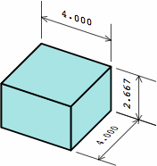
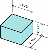
brick
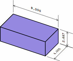
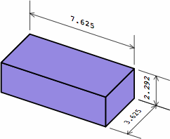
brick
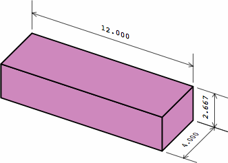
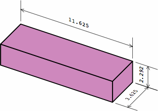
§1. Introduction. Bricks have been an important building material for millennia. Although produced in countless sizes and shapes, the vast majority are rectangular solids whose dimensions are between 2 inches (50 millimeters) and 16 in (40 mm).
The length, width, and height of a rectangular brick are measured two ways: in nominal dimensions and actual dimensions. The nominal dimension is usually a round number to simply the calculation of how many bricks will be needed in a large project. Meanwhile, each actual dimension is smaller than the corresponding nominal dimension by the anticipated thickness of the mortar joint in the completed brick wall. This amount is usually 3/8 in or 10 mm, although a bricklayer will sometimes make the joints a little larger or smaller to help the bricks line up attractively in the finished wall, or to minimize the cutting of bricks. Any precise treatment of brick sizes must carefully distinguish nominal and actual sizes throughout. If a brick is measured with a conventional ruler in the naïve manner, the actual dimensions will be yielded.
Many bricks have frogs or cores, cavities which reduce the weight of the brick and give mortar a better place to grip. Some cores are large enough to allow metal reinforcing rods to be inserted through multiple bricks. The architect selects bricks whose frogs or cores are so situated that they will not appear in the finished wall.
In the ensuing discussion, terminology generally follows American practice. Most examples employ inches rather than millimeters, although the formulas can be extended to any measuring units.
§2. Some standards. Measured nominally, many rectangular bricks have a width that is one-half the length, and a height that is one-third the length. This allows the bricks to be positioned in six different directions within the wall and still fit. The heavily-used American modular brick (here called medium brick) exhibits this characteristic. Also widely seen in the United States is a brick (here named long brick) 4 in longer. Meanwhile, what is frequently called a half brick is here termed short brick. All three sizes have roles in this report.
| chart 2A three different bricks | ||
| nominal measurement | actual measurement | |
|---|---|---|
| short brick | 
| 
|
| medium brick | 
| 
|
| long brick | 
| 
|
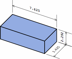
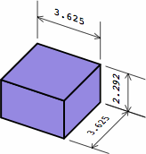
In chart 2A, the nominal measurements of the medium brick are 8 × 8/2 × 8/3 = 8 × 4 × 2 2/3 in. Each actual measurement is 3/8 in less, yielding a size of 7 5/8 × 4 5/8 × 2 7/24 in, except that industry practice usually rounds 2 7/24 to 2 1/4; in light of the permissible variation in joint thickness, this is of little consequence. In nominal measurement, the short brick's length equals its width, the medium brick's length is twice its width, while the long brick's length is thrice its width.
The American modular brick has a slightly larger counterpart in the United Kingdom: 225 × 112.5 × 75 mm nominal (British term coordinating size), 215 × 102.5 × 65 mm actual (work size); this is from a British Standard (BS 4729) that establishes sizes and shapes for a large assortment of plain and fancy bricks. Related to BS 4729 are BS 6073 for concrete blocks, and the European brick standard EN 771.
Although there is no American standard for brick sizes that might be regarded as official, custom has produced a high level of consistency. Most bricks and blocks manufactured in the United States have nominal dimensions that are multiples of 4 in (4, 8, 12, 16), or that are divisors of 16 in (16, 8, 5 1/3, 4, 3 1/5, 2 2/3, 2). Aside from these, bricks whose nominal width is 6 in are seen.
In the parlance of the brick industry, any brick that is not a rectangular solid is a shape (US) or special (UK).
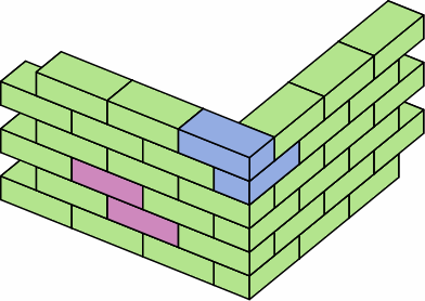
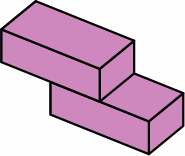
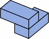
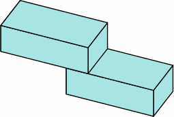
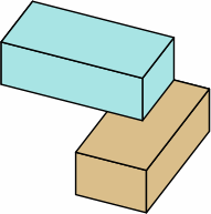
§3. Overlap. The rectangularity of the ordinary brick becomes inconvenient when a wall needs to have a corner that is not a right angle. The gist of this report is to suggest some dimensions for dogleg bricks; in other words bricks that that are L-shaped, except that the angle is something other than 90°. Motivation for the exact numbers comes from examining an ordinary wall constructed of medium bricks, as shown in chart 3A. Two pairs of bricks are excerpted for further discussion.
| chart 3A | |
|---|---|
| |
 | 
|
| parallel | perpendicular |
Because the nominal width of these medium bricks is 4 in, and the length twice that, the overlap is half the length of a brick. The nominal area of overlap between bricks of adjacent courses is therefore 16 sq in, and this is the same whether the bricks are parallel or perpendicular. Meanwhile, the actual area of overlap between bricks is the square of the actual width (3 5/8 in), which is 13 9/64 sq in.
The overlap is critical if a strong wall is to be built — it provides bonding. The dogleg bricks described below preserve the overlaps of 16 sq in nominal or 13 9/64 sq in actual when used within a brick wall whose nominal width is 4 in. For other widths, the overlap area is quadratically proportional.
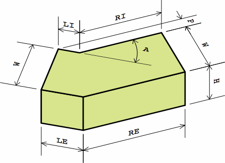
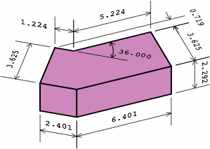
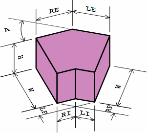
§4. Calculating dimensions. Chart 4A displays a typical dogleg brick as proposed here.
| chart 4A |
|---|
|
Whether the brick is being measured nominally or actually, the symbols mean:
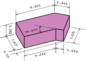
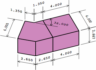
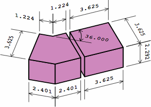
Chart 4B shows a dogleg brick compatible with the plain bricks of chart 2A. Although this example has an angle of 36°, any angle between 0° and 90° can be used, and some of the dimensions will change. For nominal or actual measurements respectively,
This is the germ of the name equal-area dogleg brick (EADB). The area of the top is the same, no matter the angle, and the area of the bottom equals the top. Too, the total area of the six sides is a constant.
| chart 4B four renderings of the same brick, and two partitionings of it; a mortar joint of 3/8 = 0.375 is assumed | ||
| nominal measurement | actual measurement | |
|---|---|---|
| interior view | 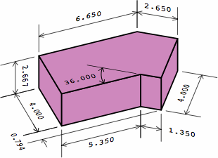
| 
|
| exterior view | 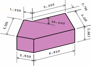
| 
|
| one brick ↑ equivalent to two bricks ↓ | one brick ↑ equivalent to two bricks plus mortar gap ↓ | |
| 
| |
The brick in chart 4B can be partitioned into the angular kernel and one extension, the extension being a rectangular solid whose length is the nominal width:
Chart 4C displays three bricks with other configurations of extensions.
| chart 4C three different bricks | ||
| nominal measurement | actual measurement | |
|---|---|---|
| angular kernel; zero extensions | 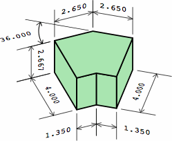 | 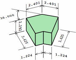
|
| one extension on each end | 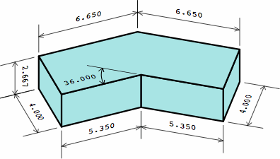 | 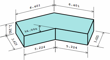
|
| two extensions on one end | 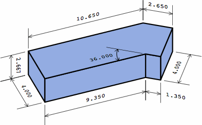 | 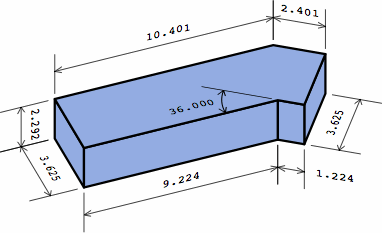
|
Here are formulas to produce the numbers, where symbol LP represents the projection of the left leg, RP of the right leg:
| chart 4D | |||
| given | |||
|---|---|---|---|
| WN | = nominal width, e.g. 4 in or 225 mm | LX | = number of extensions on the left leg, minimum zero |
| HN | = nominal height, e.g. 2 7/24 in or 65 mm | RX | = number of extensions on the right leg, minimum zero |
| J | = anticipated joint thickness, e.g. 3/8 in or 10 mm | θ | = angle, between 0° and 90° |
| first calculate | |||
| WA | = actual width = WN − J | SX | = LX + RX |
| HA | = actual height = HN − J | T | = tan (θ ÷ 2) |
| then calculate | |||
| nominal | actual | ||
| LEN | = WN × LX + WN × (1 + T) ÷ 2 | LEA | = WN × LX + WA × (1 + T) ÷ 2 |
| REN | = WN × RX + WN × (1 + T) ÷ 2 | REA | = WN × RX + WA × (1 + T) ÷ 2 |
| LIN | = WN × LX + WN × (1 − T) ÷ 2 | LIA | = WN × LX + WA × (1 − T) ÷ 2 |
| RIN | = WN × RX + WN × (1 − T) ÷ 2 | RIA | = WN × RX + WA × (1 − T) ÷ 2 |
| LPN | = LIN × sin (θ) | LPA | = LIA × sin (θ) |
| RPN | = RIN × sin (θ) | RPA | = RIA × sin (θ) |
| perimeter of top | = 4 × WN + 2 × SX × WN | perimeter of top | = 4 × WA + 2 × SX × WN |
| area of top | = WN2 + SX × WN2 | area of top | = WA2 + SX × WA × WN |
| volume | = (WN2 + SX × WN2) × HN | volume | = (WA2 + SX × WA × WN) × HA |
Here are values for the angular kernel, for some particular angles:
| chart 4E dimensions of angular kernel, with nominal width = 4 and joint = 3/8 | ||||||
| angle | nominal | actual | ||||
|---|---|---|---|---|---|---|
| LE or RE | LI or RI | P | LE or RE | LI or RI | P | |
| 0° | 2.0000 | 2.0000 | 0.0000 | 1.8125 | 1.8125 | 0.0000 |
| 5° | 2.0873 | 1.9127 | 0.1667 | 1.8916 | 1.7334 | 0.1511 |
| 10° | 2.1750 | 1.8250 | 0.3169 | 1.9711 | 1.6539 | 0.2872 |
| 15° | 2.2633 | 1.7367 | 0.4495 | 2.0511 | 1.5739 | 0.4074 |
| 20° | 2.3527 | 1.6473 | 0.5634 | 2.1321 | 1.4929 | 0.5106 |
| 25° | 2.4434 | 1.5566 | 0.6579 | 2.2143 | 1.4107 | 0.5962 |
| 30° | 2.5359 | 1.4641 | 0.7321 | 2.2982 | 1.3268 | 0.6634 |
| 35° | 2.6306 | 1.3694 | 0.7855 | 2.3840 | 1.2410 | 0.7118 |
| 40° | 2.7279 | 1.2721 | 0.8177 | 2.4722 | 1.1528 | 0.7410 |
| 45° | 2.8284 | 1.1716 | 0.8284 | 2.5633 | 1.0617 | 0.7508 |
| 50° | 2.9326 | 1.0674 | 0.8177 | 2.6577 | 0.9673 | 0.7410 |
| 55° | 3.0411 | 0.9589 | 0.7855 | 2.7560 | 0.8690 | 0.7118 |
| 60° | 3.1547 | 0.8453 | 0.7321 | 2.8589 | 0.7661 | 0.6634 |
| 65° | 3.2741 | 0.7259 | 0.6579 | 2.9672 | 0.6578 | 0.5962 |
| 70° | 3.4004 | 0.5996 | 0.5634 | 3.0816 | 0.5434 | 0.5106 |
| 75° | 3.5347 | 0.4653 | 0.4495 | 3.2033 | 0.4217 | 0.4074 |
| 80° | 3.6782 | 0.3218 | 0.3169 | 3.3334 | 0.2916 | 0.2872 |
| 85° | 3.8327 | 0.1673 | 0.1667 | 3.4734 | 0.1516 | 0.1511 |
| 90° | 4.0000 | 0.0000 | 0.0000 | 3.6250 | 0.0000 | 0.0000 |
In chart 4E, for any angle, the sum of LE or RE and RI or LE nominally is 4.000; actually 3.625. The projection is maximized at 45°.
This development assumes that, in nominal measurement, the length of an extension always equals the width of the brick; but there is no inescapable reason that this be the case, and some designers might prefer to lift the restriction. In that case, most formulas in chart 4D will need to be adjusted. The sine qua non of this whole EADB system is the zero-extension angular kernel shown in chart 4C.
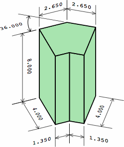
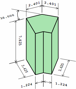
The notion of extension has a vertical counterpart: a plain brick can be laid with the length vertical, becoming a soldier. Chart 4F indicates how dogleg bricks are adapted to this purpose, with a dogleg soldier whose height equals the length of an ordinary medium brick.
| chart 4F | |
| nominal measurement | actual measurement |
|---|---|
 | 
|
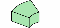
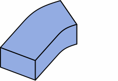
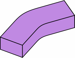
Chart 4G shows a design option: curving the angular kernel. Areas are no longer quite equal, varying with the angle, but there will still be enough area for proper bonding. A likely choice of arc is circular. Extensions, and the mortar joints between them, remain uncurved.
| chart 4G | ||
|---|---|---|
| curved kernel | 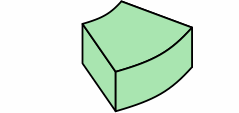
| 
|
| one extension | 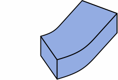
| 
|
| two extensions | 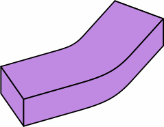
| 
|
Chart 4H shows an example of how the curved kernel is a "drop-in" replacement for an angular kernel (outlined in magenta).
| chart 4H actual measurements |
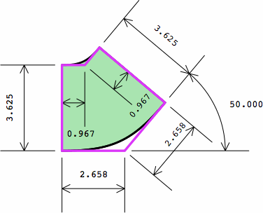
|
In the notation of chart 4D, the radius of the interior face is LIA ÷ T, and of the exterior face LEA ÷ T.
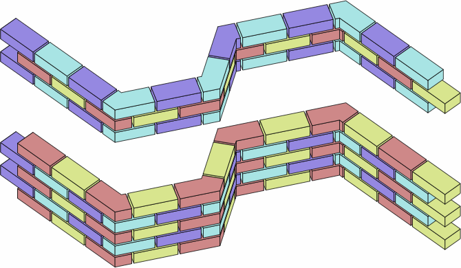
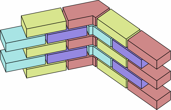
§5. Examples of walls. Chart 5A shows a wall in the familiar stretcher bond employing EADBs like those of chart 4B, except that the angle is now an arbitrarily-chosen 61°. In the top image, the bricks are drawn to their nominal size; in the middle, to their actual size, leaving gaps where mortar would go. The upper three courses are lifted to reveal detail. The bottom image is an excerpt of the middle image.
Evident is that a brick consisting of the angular kernel plus one extension is enough to achieve proper bonding; this was a motivation for the EADB system.
| chart 5A |
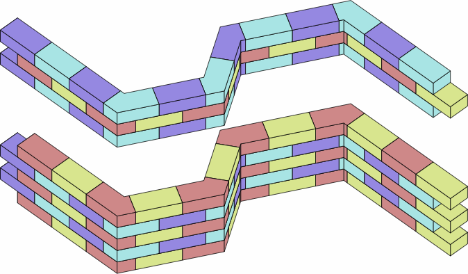
|
|
|
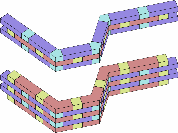
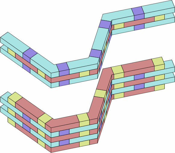
Chart 5B contains two adaptations of Flemish bond with long and short straight bricks. The top image also uses symmetric doglegs of zero or two extensions; the bottom asymmetric doglegs of two extensions.
| chart 5B |
|
|
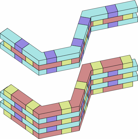
Chart 5C is a Flemish bond of more traditional proportions. It uses short and medium straight bricks; as well as angle bricks with zero extensions on one end, and with one and a half extensions on the other.
| chart 5C |
|
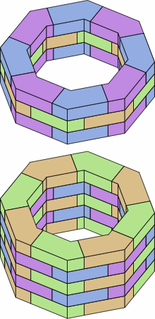
A regular octagon can be formed with 45-degree bricks, as in chart 5D. The other regular polygons of at least four sides can also be produced through suitable selection of angle.
| chart 5D |
|
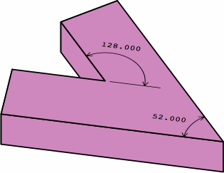
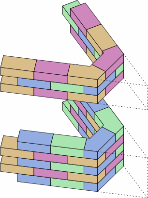
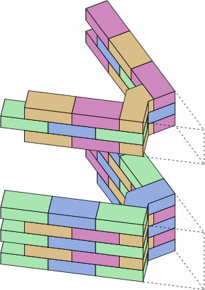
§6. Acute physical angles. Throughout the discussion above, the angle specification a brick has been limited to the range 0° to 90°. If more than 90°, the result is a brick that would have an acute physical angle. In the example of chart 6A, the image at the top shows how an angle specification of 128° leads to a physical angle of 180° − 128° = 52°. The problem is that bricks are usually made of a brittle material, and a brick with an acute physical angle such as 52° is prone to accidental breakage. The images on the bottom offer two workarounds for a wall that would have a 52° corner.
| chart 6A | |
|---|---|
| |
 | 
|
| angle specification is (180° − 52°) ÷ 2 = 64° | angle specification is 52° |
Caution: The formulas of chart 4D are not guaranteed to work with angles outside the range 0° to 90°.
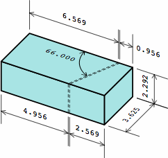
§7. Cut bricks. One way to manufacture dogleg bricks is to extrude or mold them to the right size and shape before firing, while the clay is still soft. Such was assumed in the development thus far. However, another method is sometimes preferred: making an oblique cut in a plain brick after it is fired, and then gluing the two pieces together in a different orientation. This method may be advantageous when only a few EADBs are needed, or when the factory cannot otherwise provide the desired angle.
If the brick is cut with a saw, a small part of it (the kerf) will be ground into dust, and will be missing from the finished product. The kerf depends on the thickness of the cutting blade, and here is assumed to be approximately 1/10 in. Because of the equal-area characteristic, the brick will nonetheless come out in virtually the right size.
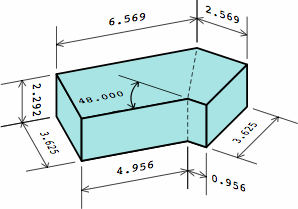
Chart 7A gives an example:
Notice that the cut-and-glued brick (7A-4) is a bit smaller than the ideal (7A-2) because of the kerf. A slightly larger mortar joint will compensate.
| chart 7A actual measurements | |||
| 7A-1 | 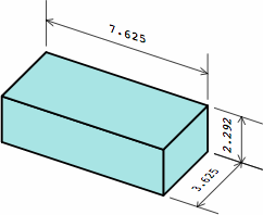
|  | 7A-3 |
|---|---|---|---|
| 7A-2 | 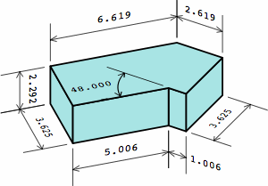
|  | 7A-4 |
The angular relationship is 66° = (180° − 48°) ÷ 2.
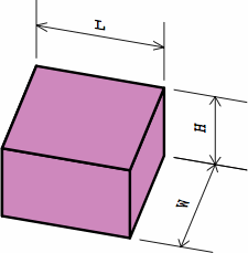
§8. Summary. Rows three through five of chart 8A review the EADBs mentioned so far; rows six through nine introduce more. Once the nominal measurements of the short brick and angular kernel are established (presumably using the formulas of chart 4D), the dimensions of the larger bricks are calculated directly by addition. For actual measurements, the joint thickness must be also reckoned.
Normally, a brick with two angular kernels will use the same angle for both. The bricks in rows six and seven, if they have angle specifications of 64°, can be used to produce other versions of the walls in chart 6A.
All EADBs satisfy the mathematical definition of a prism and are thus candidates for extrusion.
| chart 8A | ||||
| nominal measurement | actual measurement | |||
|---|---|---|---|---|
| whole brick | same dimensions as | whole brick | same dimensions as | |
| 8A-1 |  |  |  | 
|
| 8A-2 | 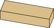 | 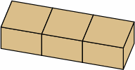 |  | 
|
| 8A-3 |  |  |  | 
|
| 8A-4 |  |  |  | 
|
| 8A-5 |  |  |  | 
|
| 8A-6 |  |  |  | 
|
| 8A-7 | 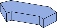 | 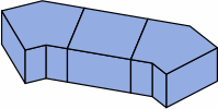 |  | 
|
| 8A-8 |  |  |  | 
|
| 8A-9 |  |  |  | 
|
If of the same height, bricks in rows 3, 6, and 8 use the same amount of raw material as the brick of row 1, and can be cut from it, the only loss being the kerf(s). Similarly, bricks in rows 4, 5, 7, and 9 use the same amount of raw material as the brick of row 2, and can be cut from it, again the only loss being the kerf(s).
Chart 8B reprises the formulas needed to calculate the dimensions of an angular kernel.
| chart 8B extracted from chart 4D | |||
| given | |||
|---|---|---|---|
| WN | = nominal width | θ | = angle |
| J | = anticipated joint thickness | ||
| first calculate | |||
| WA | = actual width = WN − J | T | = tan (θ ÷ 2) |
| then calculate | |||
| nominal | actual | ||
| LEN | = WN × (1 + T) ÷ 2 | LEA | = WA × (1 + T) ÷ 2 |
| REN | = WN × (1 + T) ÷ 2 | REA | = WA × (1 + T) ÷ 2 |
| LIN | = WN × (1 − T) ÷ 2 | LIA | = WA × (1 − T) ÷ 2 |
| RIN | = WN × (1 − T) ÷ 2 | RIA | = WA × (1 − T) ÷ 2 |
| LPN | = LIN × sin (θ) | LPA | = LIA × sin (θ) |
| RPN | = RIN × sin (θ) | RPA | = RIA × sin (θ) |
| perimeter of top | = 4 × WN | perimeter of top | = 4 × WA |
| area of top | = WN2 | area of top | = WA2 |
| 
| ||
| short brick | angular kernel | ||
Appendices.
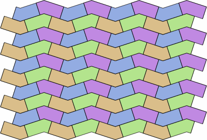
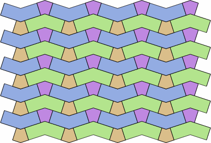
§A1. Tessellation. EADBs are of dimensions calibrated for the building of single-wythe walls, and are not particularly tessellable. The consequence is that adjustments will be necessary for many kinds of paving use. However, there is one genre of patterns that works with any angle of bricks, with examples in chart 9A.
| chart 9A |
|---|
|
|
In this arrangement, if the gap for the mortar joint is eliminated and bricks thus touch one another, everything will still fit together exactly. Omission of mortar is common in paving.
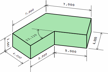
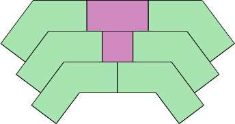
Chart 9B helps explain the limitation of tessellation. All the dogleg bricks are the same, and the two plain bricks are the short and medium bricks of chart 2A. The angle is 53.130° = 180° − 2 × atan (2). Aside from the trivial cases where the angle is 0° or 90°, this is the only angle that will allow the pink bricks to have a length which is a multiple of the width, in nominal measure. Unfortunately, 53.130° is not a convenient angle for tessellation.
| chart 9B nominal measurments |
|
|
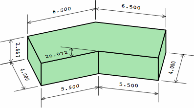
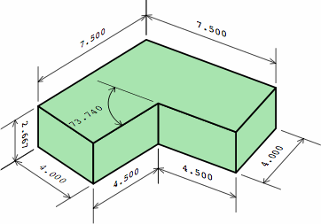
Thus far, the length of a plain brick has been restricted to being a multiple of the width, in nominal measure. If this is liberalized to allow the length of a short brick to be any multiple of half the width, two more angles become possible, as shown in chart 9C.
| chart 9C nominal measurments | |
| 
|
Still, the angles 28.072° amd 73.740° are not well suited to tessellation. These considerations also apply to walls that have multiple wythes.
§A2. A British standard. BS 4729 establishes dozens of sizes and shapes of bricks by giving their actual, rather than nominal, measurements. Of interest here are fifteen dogleg bricks covered by two of its sub-standards:
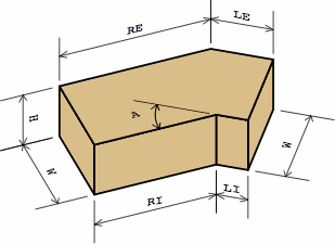
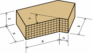
For each of these bricks, BS 4729 gives four distances, in millimeters, denoted A, B, C, and D. Chart 10A show how they relate to the measurement labels of EADBs. A grid denotes the fancy faces.
| chart 10A actual measurements | ||
| EADB | 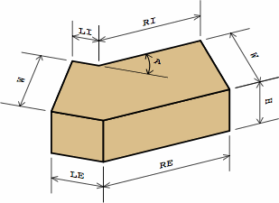
| 
|
|---|---|---|
| BS 4729 | 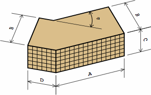
| 
|
| external — AN2 | internal — AN3 | |
For an external brick, BS 4729 does specify D (= LE) and A (= RE), but not LI and RI, because they are mathematically consequential once LE, RE, and B (= W) are selected. For an internal brick, BS 4729 does specify D (= LI) and A (= RI), but not LE and RE, for the same reason. Meanwhile, the height (C = H) is independent of all these. The angle (a = A) is measured the same in either system.
Bricks from the external and internal classifications of BS 4729 never have the same dimensions, but with EADBs the choice of which faces (if any) to make fancy is independent of the dimensions.
Chart 10B below relates BS 4729 and EADBs. Columns are numbered 1 through 16 for convenience.
In column 1 is the BS 4729 designation. Lineal measurements appear in columns 2 through 5 of the chart, and the angle is in column 6. BS 4729 recognizes only the angles 30°, 45°, and 60°; but the chart also calculates EADBs for 15° and 75° to demonstrate that the system is readily extensible.
Columns 7 through 10 contain actual lineal measurements of the EADBs. Cells colored yellow are for figures taken from BS 4729, un-rounded to their theoretical values, and applied to the EADB system. (As a practical matter, rounding brick sizes to the nearest millimeter makes sense, as greater precision is difficult to obtain in manufacture or installation.) Column 11 contains the actual area of the top of the brick (TA = "top area").
Columns 12 through 15 contain nominal lineal measurements of the EADBs, although BS 4729 says little about how nominal measurements might be calculated for dogleg bricks. Because faces sometimes meet at angles other than 90°, it is not correct to merely add the joint thickness to each actual figure. Instead, the method here is to assume that the brick is covered on every surface with a layer of mortar 5 mm thick, which distance is half of the standard joint thickness of 10 mm. Then the nominal measurements reflect the size of this enlarged polyhedron. Column 16 contains the nominal area of the top of the brick.
Because all of the BS 4729 bricks shown here have the same width (B) and the same height (C), so do the EADBs. However, the dimensions of the BS 4729 bricks were not chosen to observe the equal-area principle, so the derived EADBs cannot have equal areas.
| chart 10B distances in millimeters — areas in square millimeters — angles in degrees | ||||||||||||||||||
| 1 | 2 | 3 | 4 | 5 | 6 | 7 | 8 | 9 | 10 | 11 | 12 | 13 | 14 | 15 | 16 | |||
| BS 4729 — external | angle | EADB actual | EADB nominal | |||||||||||||||
|---|---|---|---|---|---|---|---|---|---|---|---|---|---|---|---|---|---|---|
| type | A ≈ RE | B ≈ W | C ≈ H | D ≈ LE | RE ≈ A | LE ≈ D | RI | LI | TA | RE | LE | RI | LI | TA | ||||
| 15 | 158.75 | 102.50 | 145.26 | 89.01 | 25,395 | 164.41 | 108.16 | 149.60 | 93.35 | 28,998 | ||||||||
| AN2.1 | 159 | 102 | 65 | 102 | 30 | 158.75 | 102.50 | 131.29 | 75.04 | 23,963 | 165.09 | 108.84 | 134.95 | 78.70 | 27,426 | |||
| AN2.2 | 159 | 102 | 65 | 102 | 45 | 158.75 | 102.50 | 116.29 | 60.04 | 22,426 | 165.82 | 109.57 | 119.22 | 62.97 | 25,739 | |||
| AN2.3 | 159 | 102 | 65 | 102 | 60 | 158.75 | 102.50 | 99.57 | 43.32 | 20,712 | 166.64 | 110.39 | 101.68 | 45.43 | 23,858 | |||
| 75 | 158.75 | 102.50 | 80.10 | 23.85 | 18,716 | 167.59 | 111.34 | 81.26 | 25.01 | 21,667 | ||||||||
| 15 | 215.00 | 102.50 | 201.51 | 89.01 | 31,161 | 220.66 | 108.16 | 205.85 | 93.35 | 35,326 | ||||||||
| AN2.4 | 215 | 102 | 65 | 102 | 30 | 215.00 | 102.50 | 187.54 | 75.04 | 29,729 | 221.34 | 108.84 | 191.20 | 78.70 | 33,754 | |||
| AN2.5 | 215 | 102 | 65 | 102 | 45 | 215.00 | 102.50 | 172.54 | 60.04 | 28,192 | 222.07 | 109.57 | 175.47 | 62.97 | 32,067 | |||
| AN2.6 | 215 | 102 | 65 | 102 | 60 | 215.00 | 102.50 | 155.82 | 43.32 | 26,478 | 222.89 | 110.39 | 157.93 | 45.43 | 30,186 | |||
| 75 | 215.00 | 102.50 | 136.35 | 23.85 | 24,482 | 223.84 | 111.34 | 137.51 | 25.01 | 27,996 | ||||||||
| BS 4729 — internal | angle | EADB actual | EADB nominal | |||||||||||||||
| type | A ≈ LI | B ≈ W | C ≈ H | D ≈ RI | RE | LE | RI ≈ D | LI ≈ A | TA | RE | LE | RI | LI | TA | ||||
| 15 | 64.74 | 177.24 | 51.25 | 163.75 | 23,421 | 70.40 | 182.90 | 55.59 | 168.09 | 26,831 | ||||||||
| AN3.1 | 164 | 102 | 65 | 51 | 30 | 78.71 | 191.21 | 51.25 | 163.75 | 24,853 | 85.05 | 197.55 | 54.91 | 167.41 | 28,402 | |||
| AN3.2 | 164 | 102 | 65 | 51 | 45 | 93.71 | 206.21 | 51.25 | 163.75 | 26,389 | 100.78 | 213.28 | 54.18 | 166.68 | 30,089 | |||
| AN3.3 | 164 | 102 | 65 | 51 | 60 | 110.43 | 222.93 | 51.25 | 163.75 | 28,103 | 118.32 | 230.82 | 53.36 | 165.86 | 31,970 | |||
| 75 | 129.90 | 242.40 | 51.25 | 163.75 | 30,099 | 138.74 | 251.24 | 52.41 | 164.91 | 34,161 | ||||||||
| 15 | 115.99 | 172.24 | 102.50 | 158.75 | 28,161 | 121.65 | 177.90 | 106.84 | 163.09 | 32,034 | ||||||||
| AN3.4 | 159 | 102 | 65 | 102 | 30 | 129.96 | 186.21 | 102.50 | 158.75 | 29,593 | 136.30 | 192.55 | 106.16 | 162.41 | 33,605 | |||
| AN3.5 | 159 | 102 | 65 | 102 | 45 | 144.96 | 201.21 | 102.50 | 158.75 | 31,130 | 152.03 | 208.28 | 105.43 | 161.68 | 35,292 | |||
| AN3.6 | 159 | 102 | 65 | 102 | 60 | 161.68 | 217.93 | 102.50 | 158.75 | 32,844 | 169.57 | 225.82 | 104.61 | 160.86 | 37,173 | |||
| 75 | 181.15 | 237.40 | 102.50 | 158.75 | 34,840 | 189.99 | 246.24 | 103.66 | 159.91 | 39,364 | ||||||||
| 15 | 115.99 | 228.49 | 102.50 | 215.00 | 33,927 | 121.65 | 234.15 | 106.84 | 219.34 | 38,362 | ||||||||
| AN3.7 | 215 | 102 | 65 | 102 | 30 | 129.96 | 242.46 | 102.50 | 215.00 | 35,359 | 136.30 | 248.80 | 106.16 | 218.66 | 39,934 | |||
| AN3.8 | 215 | 102 | 65 | 102 | 45 | 144.96 | 257.46 | 102.50 | 215.00 | 36,896 | 152.03 | 264.53 | 105.43 | 217.93 | 41,620 | |||
| AN3.9 | 215 | 102 | 65 | 102 | 60 | 161.68 | 274.18 | 102.50 | 215.00 | 38,610 | 169.57 | 282.07 | 104.61 | 217.11 | 43,501 | |||
| 75 | 181.15 | 293.65 | 102.50 | 215.00 | 40,605 | 189.99 | 302.49 | 103.66 | 216.16 | 45,692 | ||||||||
| 1 | 2 | 3 | 4 | 5 | 6 | 7 | 8 | 9 | 10 | 11 | 12 | 13 | 14 | 15 | 16 | |||
| in all cases: W ≈ B = 102.50 H ≈ C = 65.00 | in all cases: W ≈ B = 112.50 H ≈ C = 75.00 | |||||||||||||||||
The fundamental dimensions in BS 4729 are 225 mm for nominal brick size, and 10 mm for the mortar joint. Here are derivations of some other measurements:
| chart 10C | |
|---|---|
| distance | explanation |
| 215 | 225 − 10 |
| 159 | 158.75 = 3/4 × 225 − 10 |
| 102 | 102.50 = 1/2 × 225 − 10 |
| 46 | 46.25 = 1/4 × 225 − 10 |
| 65 | 1/3 × 225 − 10 |
| 164 | 163.75 = 3/4 × 225 − 5 |
| 51 | 51.25 = 1/4 × 225 − 5 |
| 215 | 163.75 + 51.25 |
| 102.5 | 163.75 − 51.25 − 10 |
The BS 4729 standard is very popular, with nearly all major British brick manufacturers offering its principal sizes and shapes. Many have gone further by extending the system with their own compatible sizes and shapes.
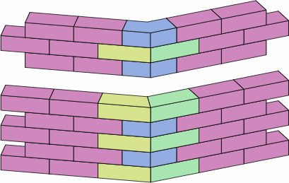
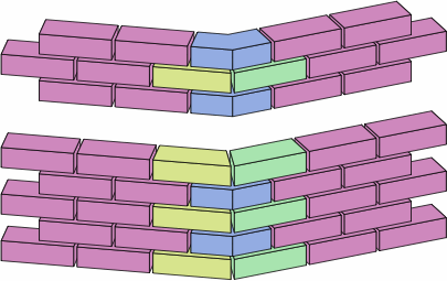
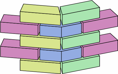
§A3. Trapezoidal bricks. The wall in chart 5C employs a dogleg brick with an extension whose length is one and a half times the width. Once fractions become eligible, one can make a brick that uses only half of an angular kernel, resulting in a trapezoid. Chart 11A, similarly to chart 5A, shows a wall using such bricks, drawn in nominal and then actual size, followed by an excerpt.
| chart 11A |
|---|
|
|
|
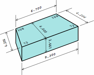
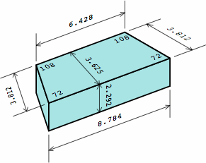
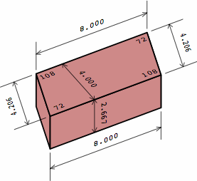
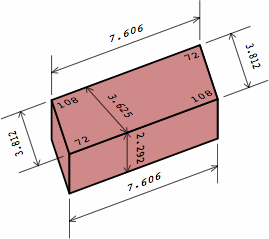
Chart 11B shows the four different bricks used in chart 11A, color-coded to match. Each trapezoidal brick is equivalent to half an angular kernel plus three-quarters of a medium brick; the yellow and green bricks are mirror images of each other. Each corner of a trapezoid is marked with its angle; for the reasons explained in section 6, extreme acute angles have to be avoided. On the dogleg brick, the length of each extension is half the width of the brick.
| chart 11B four different bricks | ||
| nominal measurement | actual measurement | |
|---|---|---|
| trapezoidal brick | 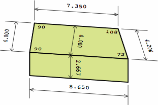 | 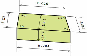
|
| trapezoidal brick | 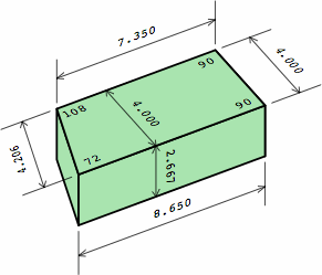 | 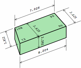
|
| ordinary medium brick | 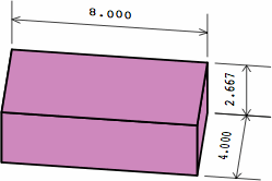 | 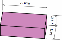
|
| ordinary dogleg brick | 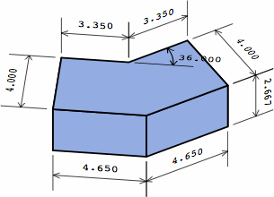 | 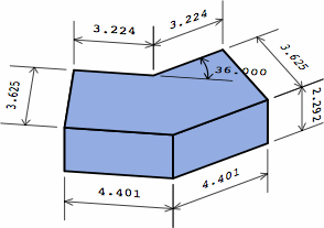
|
Chart 11C introduces two more trapezoidal bricks, each equivalent to a short brick with half an angular kernel attached to each end. In nominal measurement, all these trapezoidal bricks share the equal-area characteristic with the ordinary medium brick; in actual measurement, a very close approximation is maintained.
| chart 11C two different bricks | |
| nominal measurement | actual measurement |
|---|---|
 | 
|
 | 
|
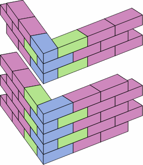
A designer must be wary of selecting the bricks whose dimensions are in chart 11B, and then arranging them as in chart 11D.
| chart 11D caution required | |
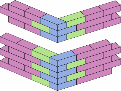 | 
|
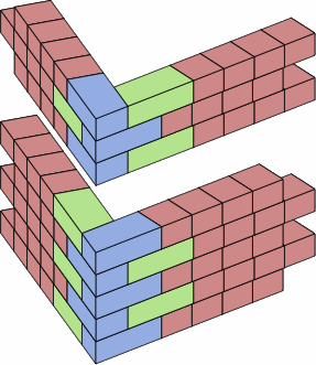
The problem is that the vertical joints will not line up quite right. In nominal size, two short bricks equal one medium brick, and chart 11E performs such a substitution to make the inaccuracy conspicuous.
| chart 11E unaligned joints | |
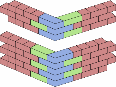 | 
|
The green bricks are too long relative to the blue bricks. The magnitude of the offset equals, nominally, the oblique width of a trapezoidal brick minus the orthogonal width. In the brick of chart 11F, this is 4.206 − 4.000 = 0.206.
| chart 11F nominal measurements |

|
With medium bricks (as in chart 11D) the inaccuracy will not be obvious, and the bricklayer may be able to fix the problem by making some vertical joints a little larger than 3/8 in, and others a little smaller. High-precision work would call for cutting the green bricks.
§A4. Two wythes. Although the equal-area principle does not immediately extend to walls of multiple wythes, an adaptation for the two-wythe case is certainly possible.
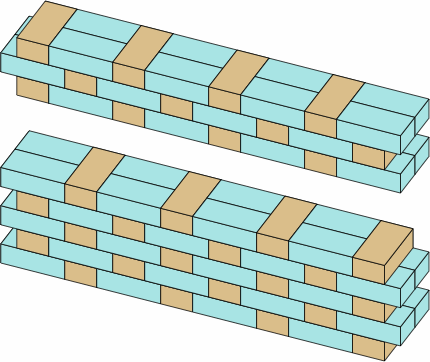
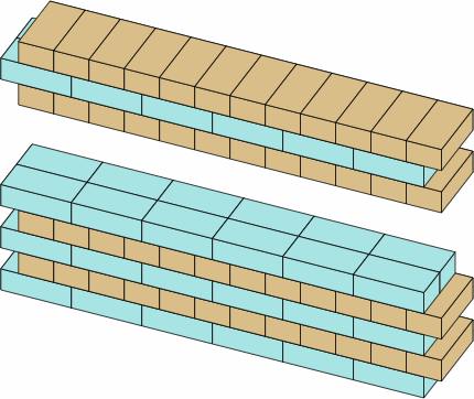
Throughout history, many bonds have been used for two-wythe walls, but Flemish and English are chosen here for examples because they have been among the most popular, and because a dogleg-brick scheme that works with them will work with most other bonds. Chart 12A displays straight wall sections in each of these bonds. Note that the overlap of bricks is sometimes smaller than encountered in previous sections. For bricks of the dimensions of chart 2A, overlap in these bonds is nominally 2 in × 4 in = 8 sq in, or actually 1 5/8 × 3 5/8 = 5 57/64 sq in. Although this area is only about half of what has been discussed above, centuries of bricklaying have revealed it to be sufficient in a multi-wythe brick wall that is designed properly in its other aspects.
| chart 12A | |
|---|---|
| flemish bond | english bond |
 | 
|
 | 
|
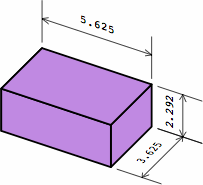
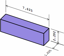
In order to make corners and ends of walls line up, these two-inch intervals necessitate two sizes of rectangular brick beyond those introduced so far. They appear in chart 12B, with the medium and short brick for comparison. The long brick rarely appears in historical brickwork, builders having generally preferred a length-to-width ratio of approximately 2-to-1.
| chart 12B four different bricks | ||
| nominal measurement | actual measurement | |
|---|---|---|
| three-quarters brick | 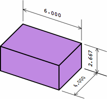
| 
|
| queen closer | 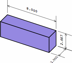
| 
|
| medium brick as in chart 2A | 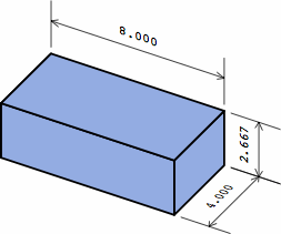
| 
|
| short brick as in chart 2A | 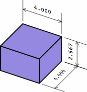
| 
|
Many builders will not use anything smaller than a queen closer or short brick (42 2/3 cu in nominally), because a very small brick necessarily has a small total bonding area. Unless the brick is located in an interior wythe of a wall with at least three wythes, it is at risk of falling out of the finished wall.
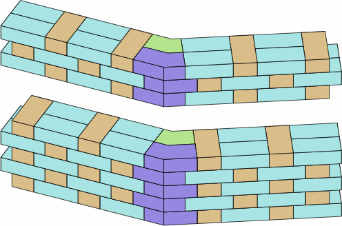
Chart 12C proposes two dogleg bricks to serve the two-wythe wall. For this example, an angle of 29° is arbitrarily selected. The brick in the top row is an ordinary angular kernel with, on one end, an extension whose length is nominally half the width. In the bottom row is a brick consisting of an angular kernel with extensions on both ends. These extensions are of whatever length happens to make it true that, nominally, LI of the outside brick equals LE of the inner (2.517); and RI of the outside brick equals RE of the inside (4.517). The actual measurements of LI, LE, RI, and RE differ, and will vary with the angle.
| chart 12C two different bricks | ||
| nominal measurement | actual measurement | |
|---|---|---|
| inside brick | 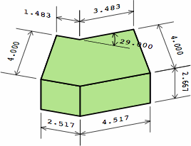 | 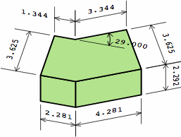
|
| outside brick | 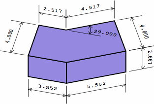 | 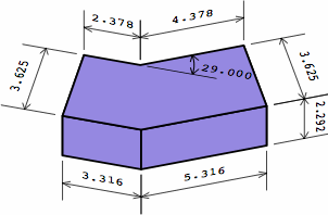
|
More broadly, extensions of any length can be used as long as outside LI equals inside LE and outside RI equals inside RE. As long as the extension is not of negative length, bonding area will be satisfactory.
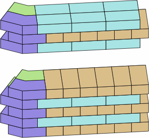
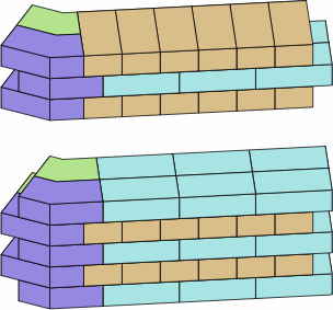
Chart 12D at the top shows a wall in Flemish bond with the bricks of chart 12C, while the bottom images are two phasings of English bond. In all of these suggested layouts, the placement of dogleg bricks in one course is the mirror image of that in the courses immediately above and below, even when not all the bricks are drawn.
| chart 12D | |
|---|---|
| |
 | 
|
Usually, it is not possible to find angle bricks that will carry the bond pattern rigorously through the corner.
Chart 12E is similar to chart 12C, except it shows an outer brick whose projections are probably too long to be practicable.
| chart 12E two different bricks | ||
| nominal measurement | actual measurement | |
|---|---|---|
| inside brick | 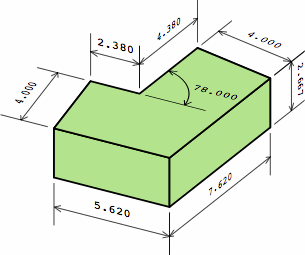 | 
|
| outside brick possibly infeasible | 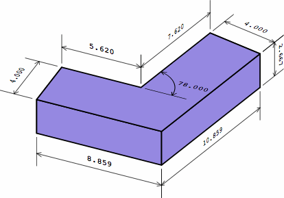 | 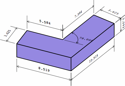
|
A remedy is revealed in chart 12F, where the shorter leg of the outer brick has been reduced by the size of a short brick. The longer leg could be reduced as well.
| chart 12F | ||
| nominal measurement | actual measurement | |
|---|---|---|
| outside brick improved | 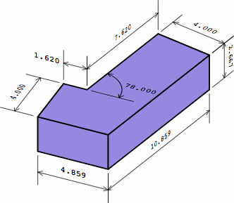 | 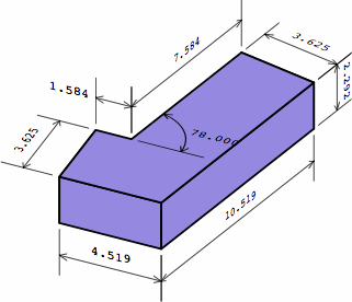
|
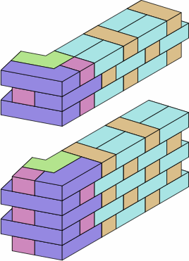
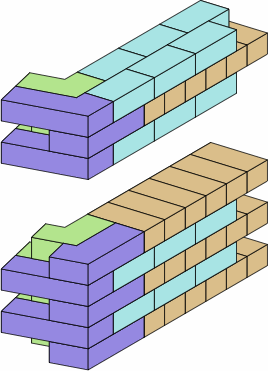
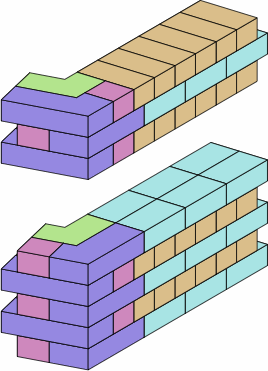
Chart 12G shows several ways to use the brick from chart 12F.
| chart 12G | ||
|---|---|---|
| 
| 
|
Colophon. This page was prepared on an Apple Macintosh running OS X. Most of the html was written with an ordinary text editor, although number-filled charts such as 10B were generated by a C++ program under XCode.
The images required multiple steps: