British Standard 4729 offers recommendations for special shapes and sizes of clay and calcium silicate bricks, although the guidance would apply equally well to bricks made of concrete or other materials. Most of the specifications are for bricks that are not rectangular in shape; for instance, some are curved to accommodate a circular wall, some are wedge-shaped for building an arch, some have chamfers or rounded edges for aesthetic interest, and others have non-right angles to facilitate the construction of a wall that has a oblique corner.
This report concentrates on the last of these categories, in particular the oblique bricks of substandards AN (angle and cant), BN (bullnose), and PL (plinth). For each brick, the Standard provides enough information to fully define its geometry, but the document does not attempt to list all the brick's dimensions. Because the missing figures may be of interest to architects and bricklayers doing precise work, this report provides drawings of each brick measured in many directions beyond those given in the Standard. Calculation involved elementary yet sometimes lengthy geometric and trigonometric procedures.
In accordance with BS 4729, angles are given in degrees, and distances are given in millimeters. While the Standard rounds each distance to the nearest whole millimeter, distances are here written to two decimal places, for two reasons: some of the theoretical values require two decimal places; and the extra precision may benefit the reader who is using the numbers for further computation. Still, in practical manufacture and installation of bricks, rounding to the nearest whole millimeter is quite sufficient.
The Standard's fundamental dimensions are 225 mm for the nominal brick size, and 10 mm for the mortar joint, resulting in 215 mm for the actual brick size. Table one contains derivations of some other measurements:
| table one | |
|---|---|
| distance | explanation |
| 215 | 225 − 10 |
| 159 | 158.75 = 3/4 × 225 − 10 |
| 102 | 102.50 = 1/2 × 225 − 10 |
| 46 | 46.25 = 1/4 × 225 − 10 |
| 65 | 1/3 × 225 − 10 |
| 164 | 163.75 = 3/4 × 225 − 5 |
| 51 | 51.25 = 1/4 × 225 − 5 |
| 215 | 163.75 + 51.25 |
| 102.5 | 163.75 − 51.25 − 10 |
Table two has links to eighteen sets of drawings containing the dimensional information for some bricks within the AN substandard. An example and explanation follow.
| table two | |||
|---|---|---|---|
| type | 30° | 45° | 60° |
| squint — 164 & 51 mm | AN.1.1 | AN.1.2 | AN.1.3 |
| external dogleg — 159 & 102 mm | AN.2.1 | AN.2.2 | AN.2.3 |
| external dogleg — 215 & 102 mm | AN.2.4 | AN.2.5 | AN.2.6 |
| internal dogleg — 164 & 51 mm | AN.3.1 | AN.3.2 | AN.3.3 |
| internal dogleg — 159 & 102 mm | AN.3.4 | AN.3.5 | AN.3.6 |
| internal dogleg — 215 & 102 mm | AN.3.7 | AN.3.8 | AN.3.9 |
Here is the example:

| 
|

| 
|

| 
|
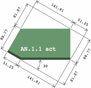
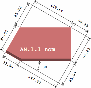
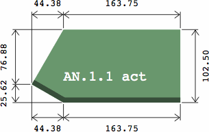
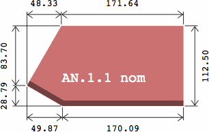
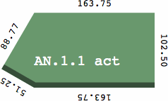
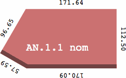
Each sextet of drawings refers to one brick, each image being a view of the brick's "footprint" from above, overwritten with the pertinent Standard number and a designation of "act" for actual, and "nom" for nominal. The dark stripes signify the fancy faces of the brick. As this is a top view, only the edges of the fancy faces are visible, and the height of the brick is immaterial. Most of these bricks are asymmetric, and their mirror images are not shown but easily deduced.
The three green images on the left display the actual size, as called for in the Standard; they are simply different ways of measuring exactly the same brick. Meanwhile, the three red images on the right display a calculation of what the slightly larger nominal size would be. The method of figuring this is to assume that each face of the (actual-size) brick is covered with a layer of mortar 5 mm thick, that being half the presumed size of a mortar joint, which is 10 mm. The dimensions of the polyhedron so produced are the brick's nominal measurements. For a rectangular brick the difference between a nominal and an actual dimension is 10 mm, but with oblique angles the difference will usually be something else.
While the top two rows within each sextet are highly detailed, the bottom row, which is redundant, serves merely as a quick reference to the lengths of the edges.
All drawings were produced to the same scale, but some computer browsers may take liberties when rendering the images.
The Standard calls for only three angles, 30°, 45°, and 60°, but others are quite feasible, and some manufacturers state a willingness to produce them.
Links to the next set of drawings are in table three below, which is organized quite differently from table two. Covered are these substandards:
Among the 18 cant bricks of AN.10, AN.11, and AN.18, there are variations in the placement and depth of chamfers, but there are only three different footprints.
Similarly, among the 36 bullnose bricks of BN.21, BN.22, and BN.23 there are variations in the placement and radius of rounded edges, as well as in the brick's overall height, but again only three different footprints, which happen to be the same as those of the AN bricks.
These AN and BN categories are in that sense functionally equivalent, and three sextets of drawings therefore suffice for 54 bricks. Because each image applies to many different bricks, it has dark stripes to represent any edge that might be chamfered or rounded. These bricks are frequently used as the top course on a brick wall, so the top of the brick as well as selected sides will often have a fancy finish.
Unlike the AN bricks of table two, the footprint of each of these bricks has an axis of reflective symmetry.
| table three | ||
|---|---|---|
| angle | applies to | |
| 30 degrees | AN.10.1 – AN.10.2
AN.11.1 – AN.11.2 AN.18.1 – AN.18.2 | BN 21.1 – BN 21.4
BN.22.1 – BN.22.4 BN.23.1 – BN.23.4 |
| 45 degrees | AN.10.3 – AN.10.4
AN.11.3 – AN.11.4 AN.18.3 – AN.18.4 | BN 21.5 – BN.21.8
BN.22.5 – BN.22.8 BN.23.5 – BN.23.8 |
| 60 degrees | AN.10.5 – AN.10.6
AN.11.5 – AN.11.6 AN.18.5 – AN.18.6 | BN.21.9 – BN.21.12
BN.22.9 – BN.22.12 BN.23.9 – BN.23.12 |
The angled plinth bricks of BS 4729 have the same footprints as certain bricks from the AN series:
Plinth bricks have a chamfer similar to that of AN.10 and AN.11. However, AN.10 and AN.11 are intended for use on the top of a wall, while plinth bricks are intended to have more courses laid on top, so that the plinth effects a setback. Hence the plinths generally do not have a fancy finish on the top, and the double-chamfer configuation (as of AN.18) is not available.
These pages were prepared on an Apple Macintosh running OS X. The html was written with an ordinary text editor, but the images required multiple steps: