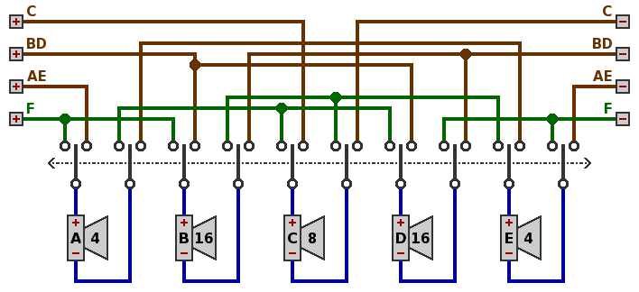
A common feature of multi-speaker cabinet design allows division of the speaker network into two subnetworks (hereafter channels), each with its own input from a separate amplifier. The two amplifiers themselves might accept input from, for instance:
This speaker arrangement is often called stereo [w], but it only vaguely resembles the notion of stereophony in high-fidelity sound reproduction. The problem here is that all the guitar speakers are presumably in one cabinet, thus the configuration is lacking the physical separation needed to produce a genuinely two-dimensional sound image. Hence the term in this report will merely be splitting.
By means of a 10-pole 2-position switch, the 8Ω canonical network can be split into three 8Ω channels, as in circuit 1 below.
| Circuit 1. |
|---|

|
Not guaranteed is that the various channels will sound the same, although with suitably selected component speakers they can come close. Of course, some guitarists may prefer that they sound different.
In the canonical network, speaker C dissipates only half the power of any other speaker, so a matched set might for example use 60-watt speakers for A, B, D and E, with 30 watts for C. If all the speakers have proportional complex impedance curves, this would give a total rating of 270 watts for the "F" channel, 120 for each of the "AE" and "BD" channels, and only 30 watts for "C" channel. These values will be assumed in the examples below.
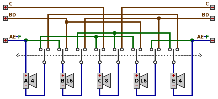
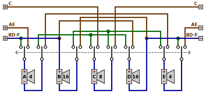
The number of poles in the switch can be reduced to 8 by combining either the "AE" and "F" connection points (circuit 2) or the "BD" and "F" connection points (circuit 3):
| Circuit 2. |
|---|
|
| Circuit 3. |
|
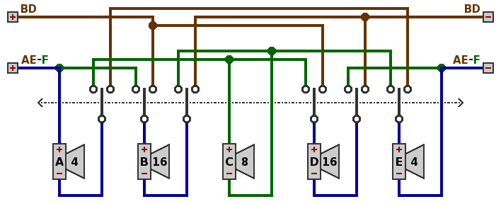
Because channel "C" can handle only one-fourth as much power as either "AE" or "BD", for some purposes it would be reasonable to omit channel "C" entirely and simplify the wiring. A 6-pole switch then becomes sufficient, as in circuit 4 which is the reduced version of circuit 2.
| Circuit 4. |
|---|
|
The same simplification can be made with circuit 1 or circuit 3.
A different approach is not to disable channel "C", but rather to replace speaker C with a higher-power unit, in this example 120 watts, so that all three channels would handle the same power. If this is done, then the full capacity of speaker C would not be used in channel "F" (canonical) operation.
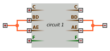
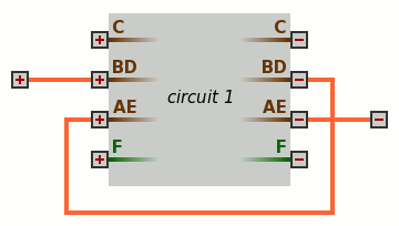
With the circuits as given above, the two or three channels yielded by splitting have no hidden connections, so that the channels may be hooked to each other as though they were separate cabinets. Below are two examples based on circuit 1, although the same idea applies to circuits 2, 3 and 4. The orange color denotes wires exterior to the cabinet which are supplied by the guitarist. In circuit 5, channel "AE" is in parallel with channel "BD" yielding 4Ω; in circuit 6, the same two channels are in series for 16Ω.
| Circuit 5. |
|---|
|
| Circuit 6. |
|
Should channel "C" be able to handle the power, it too can be wired in. On the other hand, none of channels "AE", "BD" and "C" can be connected to channel "F" in series, parallel, or otherwise, because channel "F" monopolizes all the speakers.
Further, the guitarist with two five-speaker cabinets can wire various channels of them together, as long as requirements of impedance and power handling are observed.
Another reason to avoid hidden connections is electrical safety when two amplifiers are used. In an improperly wired building, two amplifiers might draw their power from electrical outlets wired in opposite polarity, leading to a dangerously high voltage difference in the speakers connected to them.
The switch requires heavy-duty contacts. From the formula P = I2 × Z, a power of 270 watts into an impedance of 8 ohms would give a current of 5.8 amperes — if the power factor [w] were 100%, which it is not. A more likely maximum current is around 10 amperes, but adding a safety margin suggests that a 15-ampere switch is in order.