This author of this page should not be confused with a similarly-named David Barber who manufactures and sells guitar equipment.
Most links in the text below are to definitions in Wikipedia; they are marked with the symbol [w].
Background. In ordinary use, an electric guitar [w] is connected to an amplifier [w] which powers one or more speakers [w] (or less briefly loudspeakers) residing within a cabinet [w].
Because the speakers are permanently attached to the cabinet, they are often regarded as one unit. With low-power equipment, the amplifier can also be installed inside the speaker cabinet for convenience.
The amplifier and speaker influence a player's sound as much as the guitar itself, all components being manufactured in wide variety. Note the following distinction:
Guitarists frequently connect several speakers to one amplifier, among other reasons to permit the use of a higher-power amplifier (for greater loudness) than otherwise. For instance, a 200-watt [w] amplifier could damage a single speaker designed to handle a maximum of 75 watts, but four such speakers suitably wired together might work without a problem. The inverse scheme, wiring multiple amplifiers to one speaker (bridging or paralleling [w]), is less common.
Electric guitar players when connecting several speakers to one amplifier customarily limit themselves to hookups wherein the speakers are all the same, even though there are combinations of unlike speakers which are electrically and aesthetically feasible. By contrast, makers of music reproduction equipment routinely install, within one cabinet, two or more radically different speakers each tailored for one band of frequencies [w]. Frequency corresponds very closely to what musicians call pitch [w].
After some preliminary discussion, this report examines a particular scheme of connecting five guitar speakers, not all the same, to one amplifier.
Electrical considerations. In connecting speakers to an amplifer, two matters must be addressed in order to prevent damage to the equipment: impedance [w] and power [w].
Impedance. With rare exception, guitar cabinets contain dynamic speakers [w]. The impedance of such devices varies with frequency, and to be described fully requires complex numbers [w] — calculations can become quite involved. Less precise but more convenient is nominal impedance [w] which approximates the exact impedance and suffices for many practical purposes.
The unit of impedance measurement, nominal or otherwise, is the ohm [w], often symbolized by the majuscule omega (Ω) from the Greek alphabet [w]. Most speakers built today have a nominal impedance of 4Ω, 8Ω or 16Ω; because powers of two are favored by designers, 2Ω and 32Ω are occasionally seen, but other values are rare. Formulas are available to calculate the resultant impedance of several speakers wired into a network, which often differs from the impedance of any of the individual speakers.
If the speakers connected to an amplifier present too low an impedance, the amplifier will generate too high a current [w], which taken with the resistance [w] of the amplifier's internal components will generate excessive heat and damage the amplifier. On the other hand, using speakers of high impedance may lead to inefficient operation, but is not likely to harm anything. Many guitar amplifers demand a speaker network having a nominal impedance of at least 4Ω, and most others require 8Ω. Some amplifiers have several outputs, each for a different impedance, usually 4Ω, 8Ω and 16Ω. Further, some amplifiers further have protective circuitry that detects insufficient speaker impedance and shuts off the equipment before damage occurs.
Power. A dynamic speaker is limited in how much power (as measured in watts) it can accept by two main considerations:
Traditional wiring schemes for multi-speaker guitar use, along with rationales for the non-use of some other arrangements, are discussed on two pages, one without switches, and one with switches.
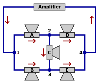
A five-speaker configuration. This scheme is the focus of this report. In the diagram below, each of the speakers is marked with a letter from "A" to "E". Within each branch a red arrow indicates that direction of current which is arbitrarily chosen to be regarded as positive. The current, being alternating [w], will in fact be moving in the negative direction half the time.

If the impedances of the individual speakers are known, the major electrical properties of this network can be calculated by means of lengthy formulas made manageable by the establishment of some intermediate results. The formulas would have been simpler were this arrangement susceptible to series or parallel [w] decomposition. The Y-Δ transform [w] is possible in either direction, but it does not seem to make the calculation easier.
Current, voltage [w] and power as figured below are instantaneous, not average, quantities; hence complex arithmetic can be used directly.
Impedance. Write ZA, ZB, ZC, ZD and ZE for the respective impedances of the five speakers; for ordinary dynamic speakers these will be a function of frequency. Then define the following quantities, which are in ohms:
Current. Let I12 stand for the current from node 1 to node 2, let I13 stand for the current from node 1 to node 3, et cetera. Meanwhile, let IN represent all the current that enters the speaker network at node 1 and exits at node 4. The branch currents, in amperes, become:
Voltage. Much as with current, let V12 stand for the voltage drop from node 1 to node 2, let V13 stand for the voltage drop from node 1 to node 3, et cetera. Similarly, let VN represent the voltage drop from node 1 to node 4 through the speaker network. The branch voltages become:
Power. Write PA, PB, PC, PD and PE for the respective power dissipations of the five speakers, and, PN for the total dissipation. Then one can calculate the following, which are in watts:
Derivation. The formulas above depend on Kirchhoff's laws [w] pertaining to current and voltage. As applied here, they read:
Physical arrangement. There are many ways that five speakers might be installed within a cabinet. It is convenient that five speakers of diameter 10 inches (about 25 centimeters), when arranged into a quincunx [w], will fit into a cabinet of the same overall size as the popular enclosure which houses four speakers of diameter 12 inches (30 cm). Both 10 and 12 inches are standard speaker sizes.

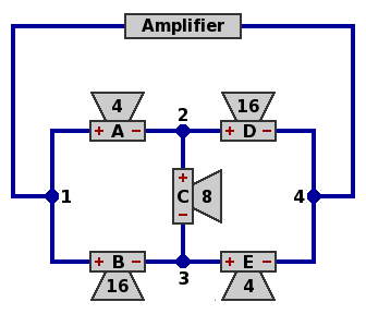
A canonical example. In the formulas above, use these nominal impedances, as in the diagram below:

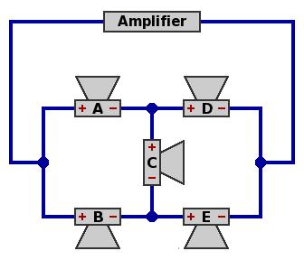
Phasing. The red plus and minus signs represent speaker connections that will yield in-phase [w] operation of the five speakers under certain circumstances, as follows. The impedance of a speaker, when examined in detail, is a function of frequency. If the impedance curves of the component speakers are approximately proportional to each other, in-phase operation can be assured at all frequencies. If not proportional, there may fail to exist a wiring plan that ensures in-phase operation. If two speakers are out of phase at some frequencies but not others, the combination will deliver an uneven frequency response [w] which may or may not be musically satisfying. In any case, out-of-phase performance is much more noticeable to the human ear at low frequencies than high.
Reactance. Another complication is that there may be frequencies at which some speakers offer capacitive reactance [w] and others offer inductive reactance, and then the designer must ensure that the equipment can handle the consequent voltages and current bouncing directly between one speaker and another, and not through the amplifier. In precise work, the designer can use laboratory instruments to measure the complex impedance of each component speaker at each of many frequencies, perhaps spaced at a ratio of 21/4 = 1.1892 (one-quarter octave [w]), and perform the calculations for the network at each frequency.
Calculations. Observe that IN may be regarded as the current produced by the amplifier, and VN as the voltage produced.
In this example, if the amplifier is delivering 3.3541 amperes at some instant, then speaker C (8Ω) is dissipating 10 watts, and each of the others (4Ω or 16Ω) is dissipating 20 watts, for a total of 90 watts.
Through suitable wiring and switches, this network can be split into subnetworks.
This canonical network can also be obtained by a simple method.
Non-canonical examples. Although the canonical selection of speaker impedances and their arrangement within the network is the most obvious choice, there are many others.

Each of the following alternatives is presented in a table showing a nominal impedance for each speaker, the nominal impedance for the network, and the power allocation. As real-world speaker impedance is more complicated than this, the examples are intended only as a guide to patterns that merit further calculations.
Examples 1A through 1D are the canonical arrangement and variations:
| Speaker | A | B | C | D | E | N | |
|---|---|---|---|---|---|---|---|
| Ex. 1A Canonical itself | Impedance | 4 | 16 | 8 | 16 | 4 | 8.000 |
| Power contribution | 22.22% | 22.22% | 11.11% | 22.22% | 22.22% | 100.00% | |
| Ex. 1B Canonical double | Impedance | 8 | 32 | 16 | 32 | 8 | 16.000 |
| Power contribution | 22.22% | 22.22% | 11.11% | 22.22% | 22.22% | 100.00% | |
| Ex. 1C Canonical half | Impedance | 2 | 8 | 4 | 8 | 2 | 4.000 |
| Power contribution | 22.22% | 22.22% | 11.11% | 22.22% | 22.22% | 100.00% | |
| Ex. 1D Canonical stretched | Impedance | 2 | 32 | 8 | 32 | 2 | 8.000 |
| Power contribution | 16.00% | 16.00% | 36.00% | 16.00% | 16.00% | 100.00% |
Each of examples 2 through 6 below is an arrangement and its dual [w]. Although there are many ways to define duals, they are in this case formed by dividing each impedance into 64Ω2. The network impedances shown approximate 8Ω, except in examples 6A and 6B, which demonstrate that other values are possible.
Within one arrangement of each pair, speaker C must be wired in the polarity reverse of that pictured in the diagram above, in order to maintain the in-phase relationship. When this occurs, the impedance value in the table is marked with a tilde (~).
| Speaker | A | B | C | D | E | N | |
|---|---|---|---|---|---|---|---|
| Ex. 2A Prime | Impedance | 2 | 16 | 16 | 16 | 4 | 7.802 |
| Power contribution | 11.21% | 23.55% | 13.46% | 33.63% | 18.15% | 100.00% | |
| Ex. 2B Dual | Impedance | 32 | 4 | ~4 | 4 | 16 | 8.203 |
| Power contribution | 11.21% | 33.63% | 13.46% | 23.55% | 18.15% | 100.00% | |
| Ex. 3A Prime | Impedance | 2 | 16 | 8 | 16 | 4 | 7.036 |
| Power contribution | 14.85% | 17.46% | 15.86% | 27.76% | 24.06% | 100.00% | |
| Ex. 3B Dual | Impedance | 32 | 4 | ~8 | 4 | 16 | 9.096 |
| Power contribution | 14.85% | 27.76% | 15.86% | 17.46% | 24.06% | 100.00% | |
| Ex. 4A Prime | Impedance | 2 | 16 | 16 | 16 | 2 | 7.040 |
| Power contribution | 11.64% | 29.45% | 17.82% | 29.45% | 11.64% | 100.00% | |
| Ex. 4B Dual | Impedance | 32 | 4 | ~4 | 4 | 32 | 9.091 |
| Power contribution | 11.64% | 29.45% | 17.82% | 29.45% | 11.64% | 100.00% | |
| Ex. 5A Prime | Impedance | 4 | 16 | 16 | 16 | 4 | 8.615 |
| Power contribution | 17.58% | 27.47% | 9.89% | 27.47% | 17.58% | 100.00% | |
| Ex. 5B Dual | Impedance | 16 | 4 | ~4 | 4 | 16 | 7.429 |
| Power contribution | 17.58% | 27.47% | 9.89% | 27.47% | 17.58% | 100.00% | |
| Ex. 6A Prime | Impedance | 2 | 16 | 4 | 16 | 2 | 5.231 |
| Power contribution | 22.62% | 16.29% | 22.17% | 16.29% | 22.62% | 100.00% | |
| Ex. 6B Dual | Impedance | 32 | 4 | ~16 | 4 | 32 | 12.235 |
| Power contribution | 22.62% | 16.29% | 22.17% | 16.29% | 22.62% | 100.00% |
Examples 7A and 7B, although not dual, each use five different impedances among the component speakers:
| Speaker | A | B | C | D | E | N | |
|---|---|---|---|---|---|---|---|
| Ex. 7A | Impedance | 2 | 16 | 8 | 32 | 4 | 8.237 |
| Power contribution | 11.28% | 19.71% | 21.15% | 17.93% | 29.94% | 100.00% | |
| Ex. 7B | Impedance | 2 | 32 | 8 | 16 | 4 | 7.770 |
| Power contribution | 17.93% | 11.28% | 21.15% | 29.94% | 19.71% | 100.00% |
In examples 8A through 8D, power among the speakers is very unevenly balanced. These are included to illustrate that achieving the correct network impedance is not sufficient to create a useful arrangement. Indeed, speaker C in example 8A has no effect. A few guitar speaker cabinets use a tweeter [w] to boost the high frequencies, and a low-power branch of one of these networks may be a good place to install such a device.
| Speaker | A | B | C | D | E | N | |
|---|---|---|---|---|---|---|---|
| Ex. 8A | Impedance | 4 | 8 | 4 | 8 | 16 | 8.000 |
| Power contribution | 22.22% | 11.11% | 0.00% | 44.44% | 22.22% | 100.00% | |
| Ex. 8B | Impedance | 4 | 16 | 4 | 8 | 16 | 8.585 |
| Power contribution | 28.38% | 8.98% | 0.44% | 43.46% | 18.74% | 100.00% | |
| Ex. 8C | Impedance | 4 | 16 | 16 | 8 | 8 | 7.714 |
| Power contribution | 26.46% | 16.93% | 2.38% | 38.23% | 16.01% | 100.00% | |
| Ex. 8D | Impedance | 4 | 8 | 4 | 16 | 8 | 8.296 |
| Power contribution | 16.93% | 16.01% | 2.38% | 26.46% | 38.23% | 100.00% |
When the component speakers are limited to 2Ω, 4Ω, 8Ω, 16Ω and 32Ω:
On the other hand, incorporating speakers whose impedances are not powers of two (which are hard to find on the market) allows the power to be precisely balanced among the five speakers. This is demonstrated in example 9, wherein Φ represents the golden ratio [w], defined as (1 + √5) ÷ 2, and approximated by 1.618.
| Speaker | A | B | C | D | E | N | |
|---|---|---|---|---|---|---|---|
| Ex. 9 Canonical balanced | Impedance | 8 ÷ Φ2 = 3.056 | 8 × Φ2 = 20.944 | 8 | 8 × Φ2 = 20.944 | 8 ÷ Φ2 = 3.056 | 8.000 |
| Power contribution | 20.00% | 20.00% | 20.00% | 20.00% | 20.00% | 100.00% |
References. Shavano has several web pages about guitar speaker wiring that are far more informative and accurate than those of most other sources. Here is an excerpt from Shavano's listing: