How multiple guitar speakers are usually wired.
Version of 7 November 2008.
Home.
Circuits 1 through 5 below are popular ways to connect multiple guitar speakers. Within each circuit, all speakers are assumed identical; otherwise the calculations become more involved.
A speaker has two terminals for attaching wires, and the red plus and minus signs in the figures below disclose exactly what should be connected to what in order to prevent the speakers from being out of phase [w], which is rarely desirable.
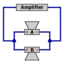
| Circuit 1 — Two speakers, parallel
Power handling capability is double that of one speaker.
Network impedance equals half the impedance of one speaker. The component speakers selected would probably be 8Ω or 16Ω, leading to a network impedance of 4Ω or 8Ω respectively.
|
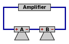
| Circuit 2 — Two speakers, series
Power handling capability is double that of one speaker.
Network impedance equals twice the impedance of one speaker. The component speakers selected would probably be 4Ω or 8Ω, leading to a network impedance of 8Ω or 16Ω respectively.
|
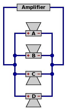
| Circuit 3 — Four speakers, parallel
Power handling capability is quadruple that of one speaker.
Network impedance equals one-fourth the impedance of one speaker. The component speakers selected would probably be 16Ω, leading to a network impedance of 4Ω.
|
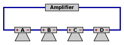
| Circuit 4 — Four speakers, series
Power handling capability is quadruple that of one speaker.
Network impedance equals four times the impedance of one speaker. The component speakers selected would probably be 4Ω, leading to a network impedance of 16Ω.
|
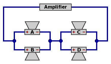
| Circuit 5A — Four speakers, parallel within series
Speakers A and B are in parallel, speakers C and D are in parallel, and the AB combination is in series with the CD combination.
Power handling capability is quadruple that of one speaker.
Network impedance equals the impedance of one speaker. Likely choices are 4Ω, 8Ω, or 16Ω.
|
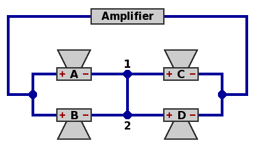
| Circuit 5B — Four speakers, intermediate arrangement
This is a rewiring of circuit 5A, with no electrical difference. Because all four speakers are the same, symmetry requires that the current from node 1 to node 2 must equal the current from node 2 to node 1; but the only way this can happen is if the current is zero. The same applies to voltage.
|
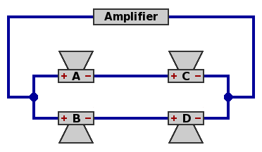
| Circuit 5C — Four speakers, series within parallel
Since the wire connecting nodes 1 and 2 in circuit 5B has no electrical activity, it can be removed. Now speakers A and C are in series, speakers B and D are in series, while the AC combination is in parallel with the BD combination.
Power handling capability remains quadruple that of one speaker.
Network impedance remains equal to the impedance of one speaker. Again, likely choices are 4Ω, 8Ω, or 16Ω.
Result: series-within-parallel (circuit 5C) gives the same performance as parallel-within-series (circuit 5A) when all four speakers are equal.
|
Cabinets themselves can be wired to one another according to the same principles as their component speakers; this is usually worthwhile only with an amplifer that delivers very high power. For instance, two identical 8Ω cabinets in parallel yield a network impedance of 4Ω. Wired instead in series, the two 8Ω cabinets would result in 16Ω of network impedance. Considerations of phase are the same as with individual speakers.
Combinations of three equal speakers are not favored because their network impedances are not the standard multiples of two (2, 4, 8, 16, 32, et cetera), as illustrated in figures 6 through 9 below. To save space, the amplifier is no longer pictured.
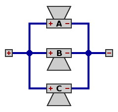
| Circuit 6 — Three speakers, parallel
Network impedance equals one-third the impedance of one speaker; with 8Ω speakers, this would be 2.6667Ω.
Total power handling capability is triple that of one speaker. All speakers dissipate the same amount of power.
|
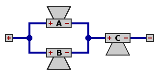
| Circuit 7 — Three speakers, parallel within series
Network impedance equals three-halves the impedance of one speaker; with 8Ω speakers, this would be 12Ω.
Total power handling capability is three-halves that of one speaker. Each of speakers A and B dissipates only one-fourth the power of speaker C, with the result that speaker C does two-thirds of the work.
|
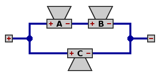
| Circuit 8 — Three speakers, series within parallel
Network impedance equals two-thirds the impedance of one speaker; with 8Ω speakers, this would be 5.3333Ω.
As with figure 7, total power handling capability is three-halves that of one speaker. Each of speakers A and B dissipates only one-fourth the power of speaker C. Again speaker C does two-thirds of the work.
|

| Circuit 9 — Three speakers, series
Network impedance equals three times the impedance of one speaker; with 8Ω speakers, this would be 24Ω.
As with figure 6, total power handling capability is triple that of one speaker. All speakers dissipate the same amount of power.
|
The 5.3333Ω impedance of circuit 8 would work satisfactorily with most 4Ω amplifers, but the great disparity (4:1 ratio) between the power dissipations of the component speakers may limit the attractiveness of this arrangement. This problem extends to most circuits containing larger numbers of speakers in an irregular arrangement. One example will suffice:
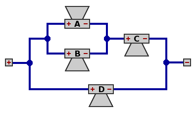
| Circuit 10 — Four speakers, parallel within series within parallel
Network impedance equals three-fifths times the impedance of one speaker; with 8Ω speakers, this turns out to be 4.8Ω, offering little trouble to a 4Ω amplifier.
Total power handling capability is five-thirds that of one speaker. Power is distributed very unevenly: for each watt dissipated by speaker A, there are 1 watt from speaker B, 4 watts from C, and 9 from D. In other words, speaker D is doing three-fifths of the work.
|


