How a two-speaker cabinet can employ switches.
Version of 7 November 2008.
Home.
The diagrams below show several ways to wire a two-speaker cabinet using switches. Of them, the first two circuits are the most frequently encountered, one reason perhaps being that 2-pole 2-position swiches are widely available and inexpensive, while switches with more poles or positions are not.
Each diagram has one pair of connections marked "M" for main, and most have a pair marked "X" for extra. The latter connection is used only when the cabinet is split between amplifiers. The speakers are letttered "A" through "D", while "NS" in the comments means no speaker.
Assumed throughout is that the all speakers in each circuit are equal. Whenever speakers are connected to each other, they will exhibit equal power dissipation because of symmetric wiring. Comments about likely impedances assume that amplifiers expect a load between 4Ω and 16Ω.
In the first five circuits, when the cabinet is not split and the speakers are wired in parallel, the network impedance is half that of one speaker; in instead wired in serial, impedance is double.
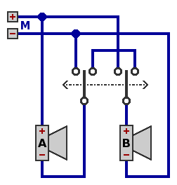
| Circuit 1.
- switch left: "A" and "B" in parallel
- switch right: "A" and "B" in series
Each speaker will probably be 8Ω.
|
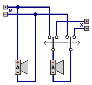
| Circuit 2.
- swich left: "A" and "B" in parallel to main, NS to extra
- switch right: "A" to main, "B" to extra
Each speaker will probably be 8Ω or 16Ω.
|
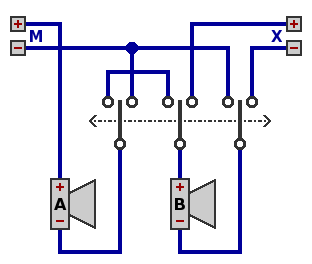
| Circuit 3.
- switch left: "A" and "B" in series to main, NS to extra
- switch right: "A" to main, "B" to extra
Each speaker will probably be 4Ω or 8Ω.
|
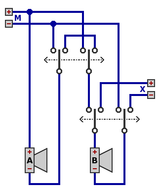
| Circuit 4.
- upper switch left:
- lower switch left: "A" and "B" in parallel to main
- lower switch right: "A" to main, "B" to extra
- upper switch right:
- lower switch left: "A" and "B" in series to main
- lower switch right: NS to main, "B" to extra
Each speaker will probably be 8Ω.
|
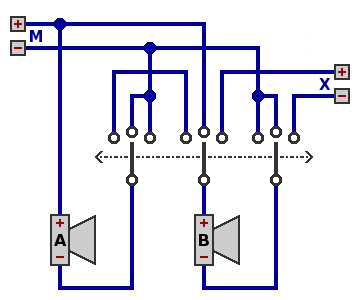
| Circuit 5.
- switch left: "A" and "B" in series to main, NS to extra
- switch middle: "A" and "B" in parallel to main, NS to extra
- switch right: "A" to main, "B" to extra
Each speaker will probably be 8Ω.
|
Naturally, a four-speaker cabinet could be created from any of the circuits above by replacing each speaker with a parallel or serial combination of suitable impedance. Here for example are two such substitutions in circuit 1:
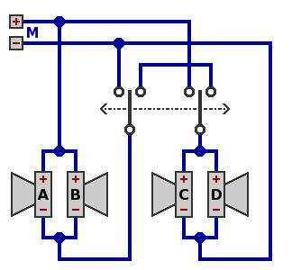
| Circuit 1P: each of "AB" and "CD" is in parallel.
- switch left: "AB" in parallel with "CD"
- switch right: "AB" in series with "CD"
Each speaker will probably be 16Ω.
|
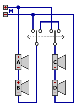
| Circuit 1S: each of "AB" and "CD" is in series.
- switch left: "AB" in parallel with "CD"
- switch right: "AB" in series with "CD"
Each speaker will probably be 4Ω.
|


