
§2. Curved pieces.
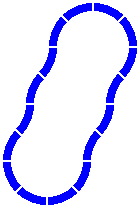
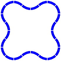
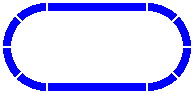
2A. Because a layout containing nothing but straight track would offer little entertainment value, practically every train set includes a number of curved track pieces. The curves are in nearly every case circular arcs, in most cases passing through 45° of angle. Commonly, all the curved pieces in a set are equal in radius. With nothing more than this, layouts can be constructed.
|
|
|
|
| Figure 2-1 | Figure 2-2 | Figure 2-3 |
|---|
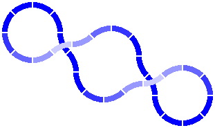
If pillars of graduated height are provided, an overpass is possible. In figure 2-4, higher altitudes are represented by sections of track in paler coloration.
|
| Figure 2-4 |
|---|
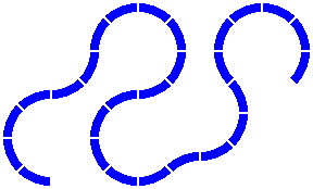
There is in fact no compulsion that the track layout be a loop, as exemplified by the serpentine design of figure 2-5. Nonetheless, most hobbyists do want to be able to include loops in their layouts; and if a satisfying variety of loops is going to be possible, then a considerable level of care is required in the design of track pieces.
|
| Figure 2-5 |
|---|
2B. Many layout examples will appear in the following sections, and for concreteness an assumption will be made: the curved track pieces have a radius of 200 millimeters [about 8 inches]. Why this number?
Note that this distance is measured to the center line of the track. If the track is 40mm wide — an average size — the inner radius is 180mm and the outer is 220mm. While nothing in this discussion requires that the track be of a particular width, the illustrations assume 40mm for typicality.
The length of one curved piece is 157.08mm [= 50 × pi], as measured along its center line. This curve is readily negotiated by the usual train car, which has a length of about 100mm.
All figures are drawn to the same scale, except where captioned otherwise. Because of mathematical rounding and graphical compression, the reader should not regard any depiction as exact. Too, the illustrations show a small gap between track pieces so the reader can see where one piece ends and the next begins.
§3. Straight pieces. The straight pieces supplied with many train sets bear no obvious relationship to the radius of curves, the manufacturers offering straight pieces as short as 50mm to fill sundry gaps; this is routinely true for brands that claim to be "compatible" or "standard". What follows in the this and the next several sections is a calculation of what lengths of straight track would fit properly, if the curved pieces of the previous section are regarded as axiomatic.
To begin with, the exact length of straight pieces makes little difference in the simplest layouts. For instance, in figure 3-1, the two straight pieces can be of any length, as long as they are equal.
|
| Figure 3-1 |
|---|
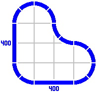
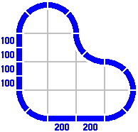
By contrast, the radius of the curves dictates the length of the straight pieces in the figures below. Any combination totaling 400mm will suffice. [The light gray lines are not part of the layout, rather being an artifice to show the alignment of different pieces.]
| 
|
| Figure 3-2 | Figure 3-3 |
|---|
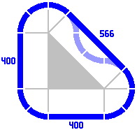
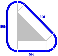
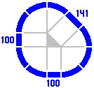
§4. The primary series. In some layouts, straight-track lengths in round numbers are not sufficient. Figure 4-1 is a modification of figure 3-2: four curved pieces [rendered in a paler color] have been replaced by one straight track. The gray lines and filled-in triangle clarify that the three straight pieces are equivalent to a right triangle. Its two legs are 400mm long each, and its hypotenuse consequently must be about 566mm long. This last number is 400 times the square root of two, itself approximately 1.414214.
| 
|
| Figure 4-1 | Figure 4-2 |
|---|
The hypotenuse length in one layout can be used as the leg length in another. For example, in Figure 4-2, the legs are 566mm leading to a hypotenuse of 800mm. Although not pictured, legs of 800mm would entail a hypotenuse of 1131mm. This substitution can be extended indefinitely; for practical reasons, such great distances would likely be implemented as several shorter pieces laid end to end.
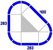
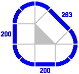
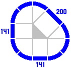
The procedure can be reversed to generate smaller triangles, as in the sequence below.
| 
| 
| 
|
| Figure 4-3a | Figure 4-3b | Figure 4-3c | Figure 4-3d |
|---|
Here is a tabulation of the numbers so far dealt with, called the primary series. The ratio of successive terms is always the square root of two.
| Table 4-A: Selected values of the Primary series | |||
|---|---|---|---|
| As an integer | To two places | Exactly | |
| 25 | 25.00 | 25 | 200 × (√2)−6 |
| 35 | 35.36 | 25 × √2 | 200 × (√2)−5 |
| 50 | 50.00 | 50 | 200 × (√2)−4 |
| 71 | 70.71 | 50 × √2 | 200 × (√2)−3 |
| 100 | 100.00 | 100 | 200 × (√2)−2 |
| 141 | 141.42 | 100 × √2 | 200 × (√2)−1 |
| 200 | 200.00 | 200 | 200 × (√2)0 |
| 283 | 282.84 | 200 × √2 | 200 × (√2)+1 |
| 400 | 400.00 | 400 | 200 × (√2)+2 |
| 566 | 565.69 | 400 × √2 | 200 × (√2)+3 |
| 800 | 800.00 | 800 | 200 × (√2)+4 |
| 1131 | 1131.37 | 800 × √2 | 200 × (√2)+5 |
| 1600 | 1600.00 | 1600 | 200 × (√2)+6 |
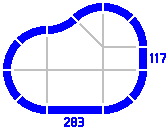
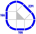
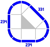
§5. The secondary series. Figure 5-1 portrays a layout that can be constructed with the track pieces developed so far. In figure 5-2 the layout has been telescoped vertically: the 283mm piece on the left has been removed, and the 400mm piece on the right has been replaced by a straight track of length 117mm [= 400 − 283], a value which does not appear in the primary series.

| 
|
| Figure 5-1 | Figure 5-2 |
|---|
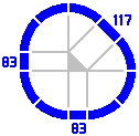
A track of length 117mm may be used to generate other lengths of straight track in the manner of figure 4-3. Here are some examples, in increasing order:
| 
| 
| 
|
| Figure 5-3a | Figure 5-3b | Figure 5-3c | Figure 5-3d |
|---|
These new numbers are members of what will be called the secondary series, introduced because its values naturally occur in many of the more complicated layouts of later sections. As with the primary series, the ratio of each term to the previous is the square root of two. Here are some values:
| Table 5-A: Selected values of the Secondary series | |||
|---|---|---|---|
| As an integer | To two places | Exactly | |
| 29 | 29.29 | 100 − (50 × √2) | 200 × (√2 − 1) × (√2)−3 |
| 41 | 41.42 | (100 × √2) − 100 | 200 × (√2 − 1) × (√2)−2 |
| 59 | 58.58 | 200 − (100 × √2) | 200 × (√2 − 1) × (√2)−1 |
| 83 | 82.84 | (200 × √2) − 200 | 200 × (√2 − 1) × (√2)0 |
| 117 | 117.16 | 400 − (200 × √2) | 200 × (√2 − 1) × (√2)+1 |
| 166 | 165.68 | (400 × √2) − 400 | 200 × (√2 − 1) × (√2)+2 |
| 234 | 234.31 | 800 − (400 × √2) | 200 × (√2 − 1) × (√2)+3 |
| 331 | 331.37 | (800 × √2) − 800 | 200 × (√2 − 1) × (√2)+4 |
| 469 | 468.63 | 1600 − (800 × √2) | 200 × (√2 − 1) × (√2)+5 |
| 663 | 662.74 | (1600 × √2) − 1600 | 200 × (√2 − 1) × (√2)+6 |
| 937 | 937.26 | 3200 − (1600 × √2) | 200 × (√2 − 1) × (√2)+7 |
| 1325 | 1325.48 | (3200 × √2) − 3200 | 200 × (√2 − 1) × (√2)+8 |
The primary and secondary series are related by a factor of (√2 − 1), which equals tan22.5°.
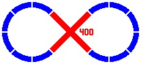
§6. Crossings. Adding important variety to layouts is a piece found in many train sets, the crossing. It contains at least two segments each of which functions as an ordinary piece of track. The segments are permanently attached to each other at the factory, so the crossing is regarded as one piece.
Real-life railroads, although they do use crossings, do not use them very often. In toy railroads by contrast, crossings are valuable for allowing increased sophistication of layout in what is often a playspace of limited area.
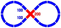
In the diagrams below, crossings are rendered in red, while single-segment pieces remain blue. Figure 6-1 shows a right-angle crossing of two straight segments each of length 400mm. Figure 6-2 is similar, except that the segments within the crossing are shorter, and plain pieces are used to fill the gaps.
| 
|
| Figure 6-1 | Figure 6-2 |
|---|
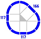
A convenient implementation of the 45° crossing uses straight segments of length 166mm from the secondary series.
| 
|
| Figure 6-3 | Figure 6-4 |
|---|
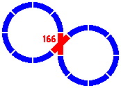
A crossing might contain one straight and one curved segment, as in figure 6-5, which is a variation on 6-4. The figure 166 refers to the length of the straight segment of the crossing; the curved section is an eighth of a circle whose radius is 1 quintimeter, as usual.
|
| Figure 6-5 |
|---|
Crossings may also be built of two curved segments, as in this one-level version of figure 2-4:
|
| Figure 6-6 |
|---|
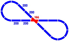
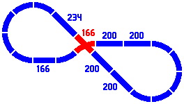
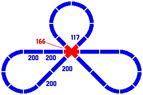
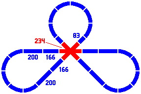
Figures 6-7 and 6-8 show two dispositions of one layout involving a three-segment crossing; all numbers come from the primary and secondary series. If the track is especially wide then the version on the right, wherein the crossing piece has segments of greater length, may be necessary to allow all the wheel paths to clear one another.
| 
|
| Figure 6-7 | Figure 6-8 |
|---|
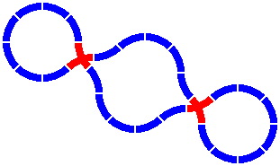
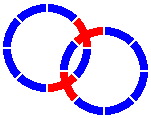
Crossings make possible the next layout, with two disjoint loops; although they intersect, trains cannot pass from one loop to the other. The crossing pieces are the same as in figure 6-6, and the distance between the centers of the two circles is 306mm [= 800 × sin22.5°].
|
| Figure 6-9 |
|---|