
§7. Switches. Greatly enhancing the realism of a toy railroad layout are switches, giving trains a choice of track on which to operate. In simpler train sets, the child simply pushes the train manually in the desired direction; in more advanced units the switch has moving parts to direct trains.
Like crossings, switches contain at least two segments of track permanently attached at the factory, and the whole switch is considered to be one piece. Unlike crossings, switches are heavily used on real-life railroads, although in that context the overall unit is called a turnout, with the term switch being reserved for the turnout's moving parts.
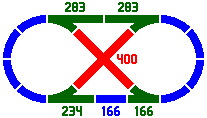
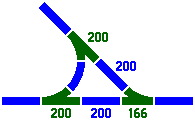
In this report, switches are rendered in green, and a number next to the switch indicates the length of the straight portion, as all curves are ordinarily equal.
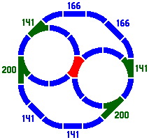
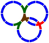
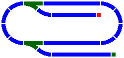
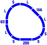
Figure 7-1 is a classic layout [the oval-eight] that uses four switches and one crossing. While its overall design is symmetrical, the wide array of track lengths from the primary and secondary series permits an asymmetrical implementation. Meanwhile, figure 7-2 shows the use of two switches in which all segments are curved.
|
|
|
| Figure 7-1 | Figure 7-2 |
|---|
Figure 7-3 displays a three-segment switch useful for creating sidings, with a center-to-center distance between parallel tracks of 117mm, from the secondary series. For interest, an oblique crossing track is added. In order to conserve screen space, this and many of the subsequent images will contain only a partial layout.
|
| Figure 7-3 |
|---|
Figure 7-4 shows the standard crossover idiom, and figure 7-5 displays a specialized switch for when one siding is ending and another beginning. Figure 7-6 demonstrates that when parallel tracks are at the 117mm spacing, an oblique track can cross one of the parallels and curve into the other.
| 
| 
|
| Figure 7-4 | Figure 7-5 | Figure 7-6 |
|---|
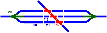
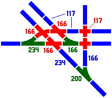
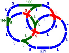
Figure 7-7 reveals what kind of complexity can be attained when crossings and switches are used together, and it shows why the secondary series is so important.
|
| Figure 7-7 |
|---|
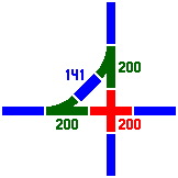
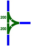
The next three figures, although simpler, are useful combinations of switches.
| 
| 
|
| Figure 7-8 | Figure 7-9 | Figure 7-10 |
|---|
§8. Miscellaneous pieces.
8A. Now that switches have been developed, it is feasible to introduce another kind of multisegment piece, the gantlet. An example, rendered in red, appears in 8-1a with its decomposition in figure 8-1b. The two segments never completely cross, but do overlap somewhat unless the track width is less than 14mm, which would be very narrow. The gantlet is categorized as a crossing because there are multiple segments, there is no switching, and trains cannot simultaneously use both segments. The distance between the centers of the circles is 414.39mm [= 400 × cos67.5° + 200 × √2 × cos22.5°]. Assuming a track width of 40mm, the maximum overlap of segments is about 26mm.
| 
|
| Figure 8-1a | Figure 8-1b |
|---|
Many other gantlets can be devised, in some cases involving one straight and one curved segment.
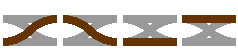
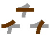
8B. The next several pieces contain both crossings and switches, and are depicted in brown. Figure 8-2 is a double crossover, a four-segment generalization of figure 7-4.
| 
|
| Figure 8-2a | Figure 8-2b |
|---|
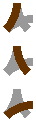
Figures 8-3 and 8-4 involve a curved segment with switches at both ends.
| 
|
| Figure 8-3a | Figure 8-3b |
|---|
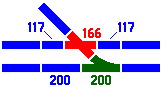
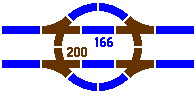
In figure 8-4a, the distance between parallel tracks is 166mm, not the 117mm seen in figure 7-3.
| 
|
| Figure 8-4a | Figure 8-4b |
|---|
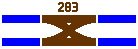
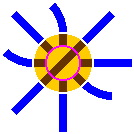
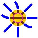
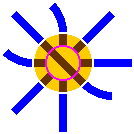
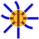
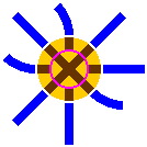
8C. The turntable, although extremely rare in real-life railroads, is a staple of toy train sets. It consists of two parts, the disk and the ring. The disk, which rotates, usually has only one segment of track and lies within the ring, fitting closely. The ring, which has several short segments of track, does not rotate but does connect to the other track in the layout. In operation, a train car rolls onto the disk, the disk rotates, and the train car leaves in a direction different from that in which it entered.
In the diagrams below, brown signifies track segments within the turntable, yellow indicates turntable areas where trains do not travel, and the pink circle separates the disk from the ring. An inner portal is where a track segment on the ring meets a segment on the disk; in other words, this is where a train car would cross the pink circle. Simlarly, an outer portal is where a segment on the ring connects to a track that is not part of the turntable; in most of the diagrams below, this is where brown meets blue.
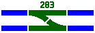
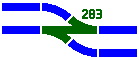
In figures 8-5 and 8-6, the outer diameter of the ring is 283mm and the inner diameter of the ring, which is also the diameter of the disk, is 166mm. Other sizes are feasible. Shown are the four natural positions of a turntable in a 45° system.
 | 
|  | 
|
| Figure 8-5a | Figure 8-5b | Figure 8-5c | Figure 8-5d |
|---|
A more efficient operation can be achieved if the disk contains a crossing instead of a lone segment. Having discharged one train car, the disk will less likely need to be rotated to accept the next car.
| 
|
| Figure 8-6a | Figure 8-6b |
|---|
The larger turntable in figure 8-7 also involves multiple segments, but no crossing.

|
| Figure 8-7 |
|---|
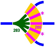
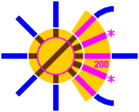
8D. Another piece favored in toy train sets but rarely seen in real trains is the roundhouse, a building, typically a quarter-circle in shape, whose purpose is to house train cars. Tracks enter and exit the structure on the concave side, and perhaps also on the convex.
The next figures show one of many possible configurations, where the yellow area denotes the footprint of the building and pink is for the tracks [of length 200mm] within it. In figure 8-8, the roundhouse is served by a five-way switch whose straight segment is 283mm long. Instead of the switch, figure 8-9 uses a turntable of outer diameter 400mm and inner diameter 283mm. Either way, the two pink tracks marked with asterisks are not part of the 45° system, and will be difficult to connect with other track in the layout.
 | 
|
| Figure 8-8 | Figure 8-9 |
|---|
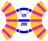
An approximate layout is given in figure 8-10, with two roundhouses back to back. The error is less than half a millimeter; it is doubtful that an exact solution exists if distances are limited to the primary and secondary series.
|
| Figure 8-10 |
|---|
8E. Two minor pieces are the barricade and the ramp. Both are used to terminate a line, and could for instance be placed at either end of the trackage of figure 2-5. Because they have little influence on layout geometry, they will receive only brief mention.
The barricade, represented by a red square in figure 8-11, is a very short section of track with an obstacle that prevents the train from rolling off the end. Barricades are widely used in real-life railroads.
The ramp by contrast is impossible in a real-life railroad, although popular in toy train sets. Symbolized by a green square in figure 8-11, it provides a gradual transition from the track to the tabletop where the tracks are laid. From there the train can proceed in any direction, rolling directly on the tabletop without regard to any track.
|
| Figure 8-11 |
|---|
9A. Not yet explored is what might happen if curved segments have a radius other than the standard so far of 1 quintimeter; first considered will be a radius of 283mm. The following two figures show layouts that use both radii. Numbers next to straight segments continue to represent length, but now letters next to curved segments will signify radius: L = 283mm, S = 200mm. Figure 9-1 is loosely derived from the figures in section 4.
|
| Figure 9-1 |
|---|
Since 283 comes from the same primary series as 200, it will generate the same secondary series; this fact mitigates the profusion of different pieces. Yet almost any switch or crossing with a curve of 200mm radius has a counterpart with a curve of 283mm radius. Beyond that, when a piece has two curved segments, it is often possible to use 200mm for one segment and 283mm for the other. After everything is settled, the catalog of pieces only gets longer.
Some multi-segment pieces are shown in figure 9-2.
|
| Figure 9-2 |
|---|
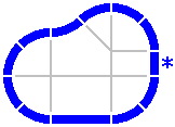
9B. Only two of many possible radii have been examined so far, and those were from the primary series. What happens if something else is selected? Figure 9-3 is taken from figure 5-2, which was used to motivate the secondary series; as before, all curved pieces are equal. If radii from the secondary series are now chosen for the curves in this layout, a tertiary series will ensue, as in table 9-A. For instance, a radius of 117mm [= 400 − (200 × √2)] leads to a length of 69mm [= 1200 − (800 × √2)] for the asterisked piece.
|
| Figure 9-3 |
|---|
| Table 9-A: Selected values of the Tertiary series | ||
|---|---|---|
| To two places | Exactly | |
| 24.26 | (300 × √2) − 400 | 200 × (√2 − 1)2 × (√2)−1 |
| 34.31 | 600 − (400 × √2) | 200 × (√2 − 1)2 × (√2)0 |
| 48.53 | (600 × √2) − 800 | 200 × (√2 − 1)2 × (√2)+1 |
| 68.63 | 1200 − (800 × √2) | 200 × (√2 − 1)2 × (√2)+2 |
| 97.06 | (1200 × √2) − 1600 | 200 × (√2 − 1)2 × (√2)+3 |
| 137.26 | 2400 − (1600 × √2) | 200 × (√2 − 1)2 × (√2)+4 |
| 194.11 | (2400 × √2) − 3200 | 200 × (√2 − 1)2 × (√2)+5 |
| 274.52 | 4800 − (3200 × √2) | 200 × (√2 − 1)2 × (√2)+6 |
9C. Not surprisingly, radii from the tertiary series can lead to a quaternary series, et cetera. To limit this propagation, one can observe that (√2 − 1) differs from (√√2)−5 by about 1.5%. [Because of the limitations of HTML, the doubled radical sign is used here to mean the square root of the square root of two, in other words the fourth root of two, approximately 1.18921.] If that error is tolerable, an alternate secondary series can be prepared, as in table 9-B.
| Table 9-B: Selected values of the Secondary series | |||
|---|---|---|---|
| Original series from table 5-A | Alternate series | ||
| To two places | Exactly | To two places | Exactly |
| 58.58 | 200 × (√2 − 1) × (√2)−1 | 59.46 | 200 × (√√2)−7 |
| 82.84 | 200 × (√2 − 1) × (√2)0 | 84.09 | 200 × (√√2)−5 |
| 117.16 | 200 × (√2 − 1) × (√2)+1 | 118.92 | 200 × (√√2)−3 |
| 165.68 | 200 × (√2 − 1) × (√2)+2 | 168.18 | 200 × (√√2)−1 |
| 234.31 | 200 × (√2 − 1) × (√2)+3 | 237.84 | 200 × (√√2)+1 |
| 331.37 | 200 × (√2 − 1) × (√2)+4 | 336.36 | 200 × (√√2)+3 |
| 468.63 | 200 × (√2 − 1) × (√2)+5 | 475.68 | 200 × (√√2)+5 |
| 662.74 | 200 × (√2 − 1) × (√2)+6 | 672.72 | 200 × (√√2)+7 |
Each entry in the alternate secondary series can be calculated by multiplying an entry in the primary series by √√2. To generate the alternate tertiary series, one multiplies each entry in the alternate secondary series by √√2 — but this merely regenerates the primary series. In other words, the alternate tertiary series is the same as the primary series. This means that the alternate quaternary series is also the alternate secondary series, similarly for higher-order series. With the total number of series reduced to two, profusion of track lengths is decreased.
Even further, it becomes convenient to regard the primary and alternate secondary series as members of one large general series wherein the ratio of consecutive terms is √√2, as in table 9-C:
| Table 9-C: Selected values of the General series | ||
|---|---|---|
| To two places | Exactly | Source |
| 84.09 | 200 × (√√2)−5 | Alternate secondary |
| 100.00 | 200 × (√√2)−4 | Primary |
| 118.92 | 200 × (√√2)−3 | Alternate secondary |
| 141.42 | 200 × (√√2)−2 | Primary |
| 168.18 | 200 × (√√2)−1 | Alternate secondary |
| 200.00 | 200 × (√√2)0 | Primary |
| 237.84 | 200 × (√√2)+1 | Alternate secondary |
| 282.84 | 200 × (√√2)+2 | Primary |
| 336.36 | 200 × (√√2)+3 | Alternate secondary |
| 400.00 | 200 × (√√2)+4 | Primary |
| 475.68 | 200 × (√√2)+5 | Alternate secondary |
| 565.69 | 200 × (√√2)+6 | Primary |
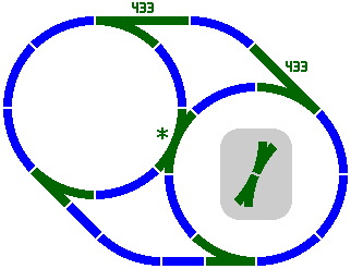
9D. Larger radii make feasible another design of switch, asterisked in figure 9-4. In this diagram all curves have a radius of 400mm. The inset shows how this switch can be regarded as two simple switches permanently connected end to end.
|
| Figure 9-4 |
|---|
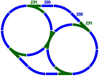
The straight section marked 433 is more precisely 432.96mm [= 800 × √2 × sin22.5°]. This number does not appear in any of the series yet encountered, and risks inducing yet another batch of track lengths. Perhaps the best method of averting this problem is to observe that 432.96 very nearly equals 200.00 [from the primary series] plus 234.31 [from the secondary]. The error is only about 0.3%, and no new track lengths are introduced. Figure 9-5 illustrates.
|
| Figure 9-5 |
|---|
If, instead, 200 is added to 237.84 from the alternate secondary series, the sum 437.84 differs from the ideal value 432.96 by about 1.1%, which is less than the 1.5% error incurred merely by adopting the alternate secondary series.
§10. Complexity. Some readers might remark this system is too involved for preschoolers, the ostensible target for toy trains, and the author is inclined to agree. [Indeed, a fair amount of trigonometry was required to verify some of the layouts above.] Straight segments of length 83mm, 100mm, 117mm, 141mm, 166mm, 200mm, 234mm and 283mm have appeared, and each fulfills a particular need. On top of that, multiple radii are permitted for curves.
Any of these segments can appear as a plain piece, or as part of switch and crossing combinations. As a result, hundreds of pieces are possible. While adult hobbyists might revel in the detail, younger children are at a real risk of becoming baffled or frustrated. Plus, the expense of collecting all the track pieces that are likely to be needed for nontrivial layouts is itself substantial.
It is important to bear in mind that all this complication is merely a consequence of having a curved track that is one-eighth of a circle — and plenty of toy train sets do exactly that. The following sections offer alternative schemes that far simpler to use.