


While most toy bricks (for instance Lego) are based on a square unit, the regular hexagon serves equally well as a basis for design because, like a square, it is tessellable.
Jeff Epler has produced some of these bricks on a 3-D printer. The present author has more recently produced more of them.
Etymology. Found in Latin is the noun later (plural lateres) meaning "brick", with the diminutive laterculus (plural laterculi) meaning "little brick", which is appropriate for the likely size of the toy bricks developed in this report. (Some people might like the English versions latercule or latercle.) The English adjective latercular follows by way of the customary procedures of derivation; someone who makes or uses these bricks could be called a laterculator; the whole process laterculation.
Although also derived from Latin, the similar-looking English words lateral and latent are unrelated.
Figure A-1 shows the two smallest bricks in a hexagonal system, bearing one and two studs respectively, the studs being the hexagonal projections on the tops of the bricks. These two bricks are the minimum for any serious construction. When a wall is formed by stacking bricks, each stud is gripped by a socket in the bottom of whatever brick is on top of it. There is enough friction in the fit to make accidental dislodging unlikely, but not so much as to prevent intentional disassembly.
| A-1 |
 

|
|---|
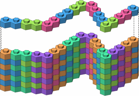
Figure A-2, using only one- and two-stud bricks, exhibits three ways of executing corners. In this illustration and many others, the top course is lifted to reveal the course beneath it, and adjacent bricks are rendered in different colors to make the pattern clearer. Dotted lines connect corresponding points.
| A-2 |
|
|---|
Sometimes several walls will meet in a tee, wye, crossing or other configuration. In this case it is practically necessary to use three-stud bricks, as in figure A-3, to ensure a strong junction.
| A-3 |


|
|---|
Figure A-4 offers three implementations of essentially the same junction, each using a three-stud brick.
| A-4a straight | 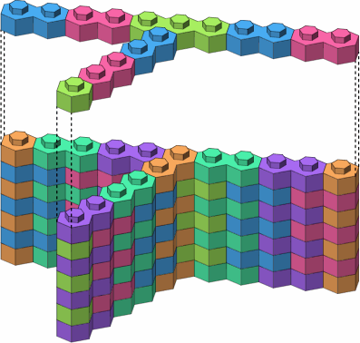
|
| A-4b angled | 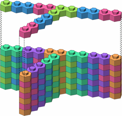
|
| A-4c triangular | 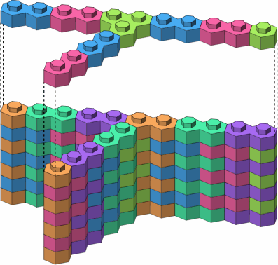
|
The arrow and wye benefit from the angled three-stud brick, as shown in figure A-5.
| A-5a | 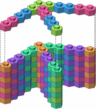
|
|---|---|
| A-5b | 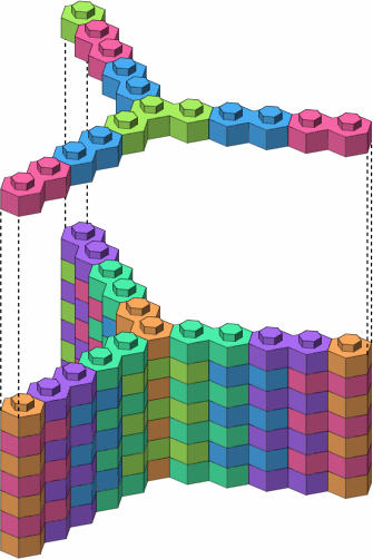
|
The possible four-stud bricks are displayed in figure A-6; colored the same are mirror-image pairs. The three bricks in the top row are the most likely to be useful.
| A-6 |


|
|---|---|


|
In figure A-7, the arrow and wye now use four-stud bricks.
| A-7a | 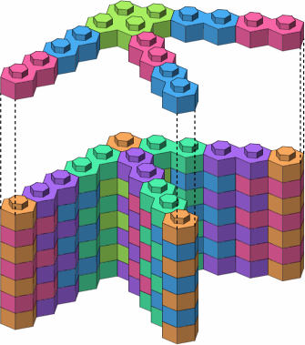
|
|---|---|
| A-7b | 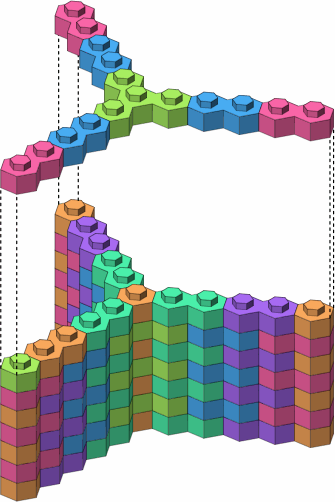
|
Figure A-8 shows straight crossings that use three-stud bricks.
| A-8a straight | 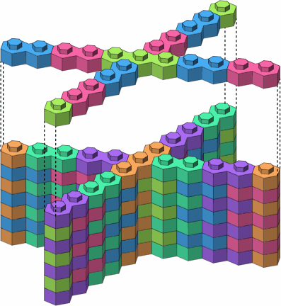
|
| A-8b angled | 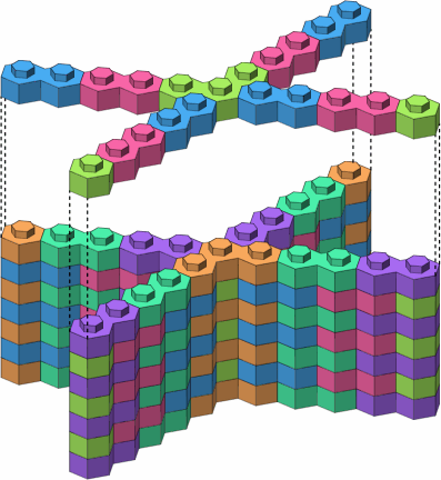
|
| A-8c triangular | 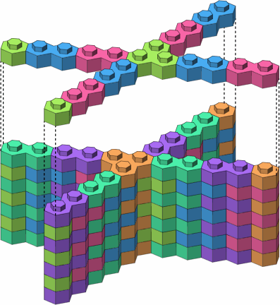
|
Other four-leg junctions are possible, as in figure A-9.
| A-9a | 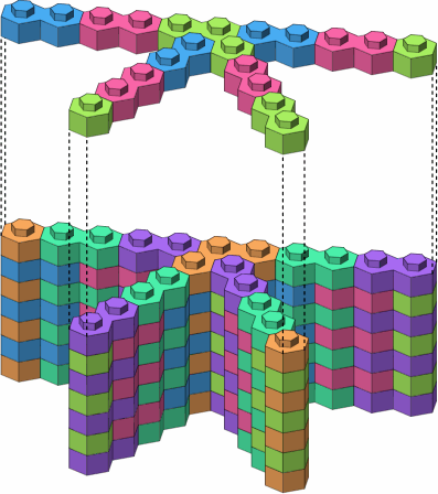
|
|---|---|
| A-9b | 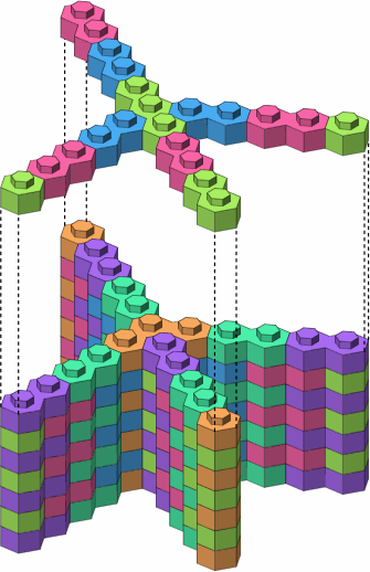
|
| A-9c | 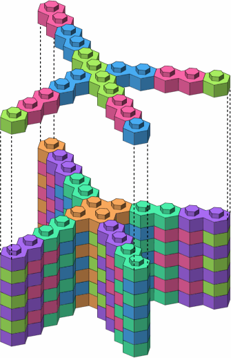
|
Figure A-10 illustrates that five- and six-leg junctions that can be built with the bricks thus far introduced.
| A-10a | 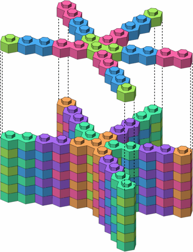
|
|---|---|
| A-10b | 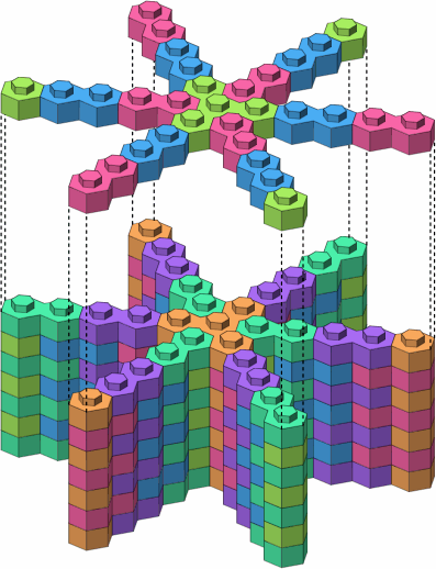
|
| A-10c | 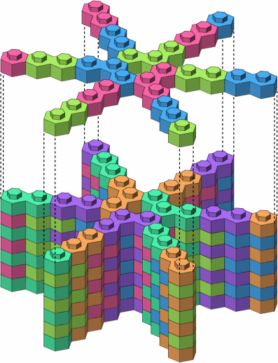
|
The possibilities for brick shapes are endless, and a manufacturer cannot feasibly offer more than few. Fortunately, a small selection, such as that of figure A-11, allows a great variety of structures to be built. The longer bricks help to span gaps.
| A-11 |


|
|---|
Figure B-1 shows some beams that are two studs wide. The two in orange, seven studs long, are mirror images of each other. The blue has seven studs along one edge and six along the other, resulting in ends that are not parallel.
| B-1 |
  
|
|---|
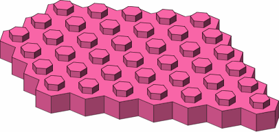
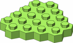
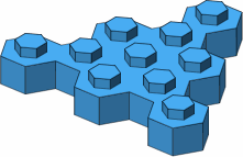
In figure B-2 are a few examples of larger bricks, among a wealth of possibilities.
| B-2 |
|
|---|
Figure C-1 shows, from a rather shallow viewing angle, the top and bottom of a seven-stud brick.
| C-1a | 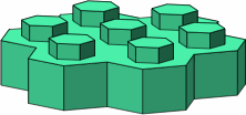
| C-1b | 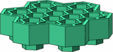
|
|---|
Figure C-2 is like C-1b but, besides being larger, is turned to show the bottoms of the sockets. The seven sockets symbolically colored in magenta are in phase, being directly underneath studs on the top of the brick. The six sockets in purple are out of phase, offering extra options in attaching one brick to another. The eighteen partial sockets (orange) along the edge are not anticipated to have any use.
| C-2 | 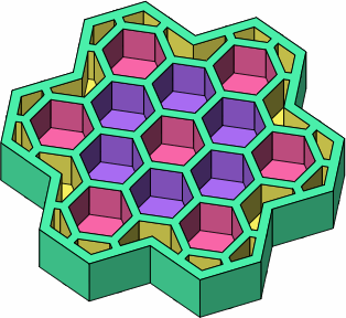
|
|---|
From viewpoints almost directly underneath the brick (figure C-3a) and from the side (C-3b) are shown a purple two-stud brick plugged into an out-of-phase location; and a magenta two-stud brick plugged into an in-phase location. Figure C-3c removes the green brick to more clearly convey the relative alignment of the magenta and purple bricks.
| C-3a | 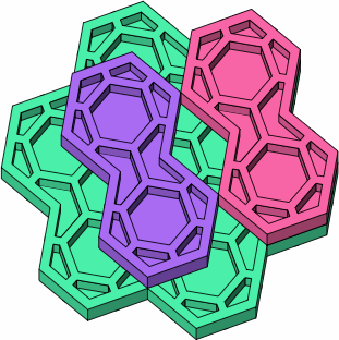
| C-3b | 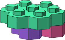
|
|---|---|---|---|
| C-3c | 
|
Support for out-of-phase attachment is the principal reason that the sides of the stud are not parallel to the sides of the brick, as is most evident on the one-stud brick. The lower brick in an out-of-phase connection will have to be smaller than the upper brick, as otherwise the upper brick's wall would interfere with at least one of the lower brick's studs.
If a brick of the type so far presented is only one stud wide, as the purple brick in figure C-3, a brick plugged in underneath it will have no opportunity for out-of-phase placement. However, out-of-phase connection becomes possible with the beams of figure B-1, because they are at least two studs wide. The smallest brick enabling out-of-phase assembly is the three-stud triangle of figure A-3.
Many of the succeeding illustrations will contain views from above and below; there should be no difficulty telling the difference.
Proceeed to page two.