

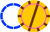

§23. Turntables. These follow the same principles as in the 45-degree and other systems.
In figures 23-1a and 23-1b, the outer diameter of each ring, β(0) = 290.62mm, was selected so that the turntable would fit into precisely the space of two curved segments. [The exact value of the inner diameter — pink circle — is not critical.] These first two diagrams differ only in what segments are on their disks; other segments are certainly possible.
The turntable in figure 23-1c has an outer diameter of α(3) = 550.55mm, and fills in the space of three curved segments of a circle. At over half a meter in diameter, this piece may be too large for practical use. Meanwhile, figure 23-1d illustrates that a turntable of the size to replace one curved segment, α(0) = 129.97, will have a disk too small to hold the typical train car. For these reasons, the remaining discussion will look at the 290.62mm turntable exclusively.
 | 
|  | 
|
| Figure 23-1a | Figure 23-1b | Figure 23-1c | Figure 23-1d |
|---|
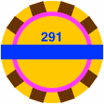
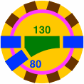
Aiding layout design is how the turntable fits into the same space occupied by certain plain segments:
 | 
| 
|
| Figure 23-2a | Figure 23-2b | Figure 23-2c |
|---|---|---|
| scale 2x | ||
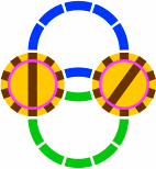
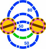
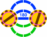
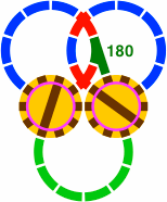
Two proximate turntables can be connected in a variety of ways. Emphasized segments are rendered in bright green:
 | 
|  | 
|
| Figure 23-3a 1 or 5 curved segments per connection | Figure 23-3b 3 curved segments per connection | Figure 23-3c 2 or 4 curved segments per connection | Figure 23-3d 0 or 6 curved segments per connection |
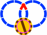
Figure 23-3d introduces a crossing of two curved segments differing from anything in figure 19-5. This new crossing is also seen in 23-4a below, while in 23-4b five such pieces are placed in an arrangement called an astrone [Italian for large star], which will fit into a layout precisely wherever a turntable would. Another drop-in replacement for the turntable is the crossing of figure 20-8f augmented with 80mm straight segments [23-4c]. Figure 23-4d shows how a succession of astrini, and consequently the other pieces of figure 19-5, will fit counsecutive outer portals of a turntable.
 |  |  | 
|
| Figure 23-4a | Figure 23-4b | Figure 23-4c | Figure 23-4d |
|---|
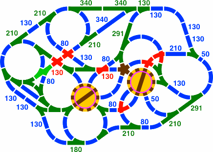
Figure 23-5 is an intricate layout involving turntables; all pieces fit exactly. The lengths of some straight segments are not indicated due to a lack of space, but all come from the alpha and beta series.
|
| Figure 23-5 |
|---|
Toward the left-hand side of figure 23-5 is a double switch rendered in vivid green; 23-6 is the same piece drawn larger. The straight segment is 210mm long.

|
| Figure 23-6 scale 4x |
This same 291mm turntable is appropriate for a 72° system [five segments per circle], which can be simulated in the 36° system by using curved segments strictly in pairs, never singly.
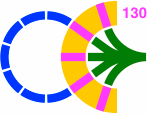
§24. Roundhouses. These are much as in the 45° system. In the example of figure 24-1, the outer diameter is 551mm like the turntable of 23-1c. The inner diameter is 291mm, like the turntable of 23-1b. Consequently the length of each track segment (rendered pink) is 130mm, long enough for nearly all toy train cars.
|
| Figure 24-1 |
|---|
Figure 24-2 shows how the five-way switch is constructed. The combination of orange segments in 24-2c is like that of figure 22-4b.
 | 
|  | 
|
| Figure 24-2a | Figure 24-2b | Figure 24-2c | Figure 24-2d |
|---|---|---|---|
| scale 2x | |||
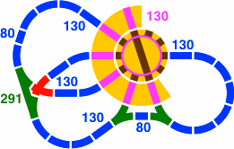
In the layout of figure 24-3, the roundhouse, now with six bays, is served by a turntable.
|
| Figure 24-3 |
|---|
Deserving a comment is the switch at the the left of figure 24-3, shown again in 24-4a and 24-4b. This double switch might have been implemented as two single switches with a straight connecting segments as in 24-4c, except that a 31mm piece is likely too short to be feasible. Either way, the adjacent crossing piece (in red) is the same as in 23-3d.
 |  | 
|
| Figure 24-4a | Figure 24-4b scale 2x | Figure 24-4c |
Figure 24-5 shows how one turntable can have two roundhouses if the total number of bays is small enough.

|
| Figure 24-5 |
|---|
There is enough space in the roundhouse to squeeze in additional bays which are not part of the 36° system; access is provided by a turntable with extra portals. Although tracks (drawn here in vivid green) may be connected to the extra bays on the convex side of the structure, such tracks cannot be relied upon to connect with the 36°-system segments.

|
| Figure 24-6 |
|---|
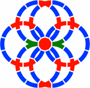
§25. More about crossings. The center piece of figure 25-1 is a five-way 130mm crossing, the same as figure 20-8f.
 |
| Figure 25-1 |
|---|
Three crossings appear in this layout, two of them new and one old; they are best understood as overlays. The components of figure 25-2 are as follows:
 | 
|  | 
|
| Figure 25-2a | Figure 25-2b | Figure 25-2c | Figure 25-2d |
|---|---|---|---|
| scale 4x | |||
The switch in 25-1 has been used all along, but is shown below as an overlay in 25-3a. Both this switch and the crossing of 25-2c are subpieces of the astrino (19-5e). In fact, the entire astrino will fit as an overlay on 25-2a; the astrino will, however, use only alternate portals. Pieces yet unseen, but suggested by overlaying, are the gantlet of 25-3b and crossing of 25-3c. Note that the crossing of 23-4a (redisplayed as 25-3d here) is not layable over the five-way 130mm switch, but rather the 291mm turntable.
 | 
|  | 
|
| Figure 25-3a | Figure 25-3b | Figure 25-3c | Figure 25-3d |
|---|---|---|---|
| scale 4x | |||
Not obvious is that the highly entangled layout of figure 25-1 is the union of two disjoint layouts:
 | 
|
| Figure 25-4a | Figure 25-4b |
|---|
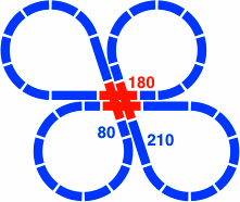
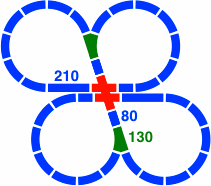
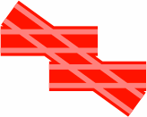
§26. Double tracks. Several cloverleaf figures derived from the figure-eights of figures 21-1 through 21-4 establish the basics of double tracking. Segments are of familiar lengths, and center-to-center distance between parallel tracks is necessarily 47.21mm [= α(−2) × cos18°].
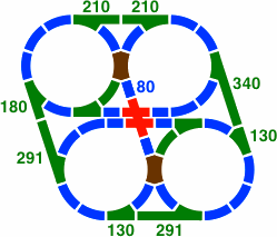
In 26-1b all red segments are 180mm, while in 26-2b the horizontal are 130mm and the oblique 180.
 | 
|
| Figure 26-1a | Figure 26-1b scale 4x |
 | 
|
| Figure 26-2a | Figure 26-2b scale 4x |
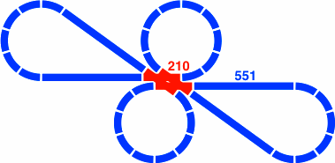
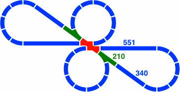
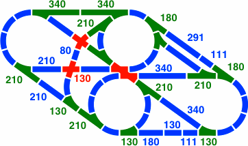
In figure 26-3b all red segments are 210 mm, while in 26-4b the horizontal are 130mm and the oblique 210.
 | 
|
| Figure 26-3a | Figure 26-3b scale 4x |
 | 
|
| Figure 26-4a | Figure 26-4b scale 4x |
Figures 26-5a and 26-5b are elaborations of 26-2a and 26-4a respectively. They were created to show that these double crossing pieces are fully compatible with the usual segments of the 36-degree system. As always, all pieces fit exactly.
 | 
|
| Figure 26-5a | Figure 26-5b |
|---|
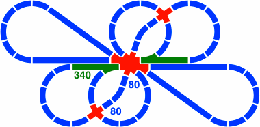
Figure 26-6 adds a segment, also 180mm, to the crossing of figure 26-1.
 | 
|
| Figure 26-6a | Figure 26-6b scale 4x |
|---|
§27. Miscellaneous.
27A. Curved segments of multiple radii, in the manner of section 9, can co-exist in the 36° system. If one radius is 200mm, the most compatible choices are 323.61mm [= 200 × Φ] and 123.61mm [= 200 ÷ Φ]. These would induce the same alpha and beta series as 200mm, helping to reduce the catalog of possible pieces. The usual caution remains that longer train cars may have trouble negotiating curves of radius under 150mm.
27B. The following are algebraic forms for trigonometric functions of the angles being used here; they are frequently helpful in verifying identities such as tan54° = tan18° + sec18°. The abundance of identities is the reason that, when the layout designer needs tracks to fit together exactly, they so often will.
Each row of the following table contains five equivalent expressions, the last an approximation.
| Table 27-A: Algebraic trigonometry | ||||
|---|---|---|---|---|
| sin18° | cos72° | 0.25 × (√5 − 1) | 0.5 × (Φ − 1) | 0.309017 |
| sin36° | cos54° | 0.25 × √(10 − √20) | 0.5 × √(3 − Φ) | 0.587785 |
| sin54° | cos36° | 0.25 × (√5 + 1) | 0.5 × Φ | 0.809017 |
| sin72° | cos18° | 0.25 × √(10 + √20) | 0.5 × √(Φ + 2) | 0.951057 |
| tan18° | cot72° | √(1 − √0.8) | Φ−1.5 × 5−0.25 | 0.324920 |
| tan36° | cot54° | √(5 − √20) | Φ−1.5 × 5+0.25 | 0.726543 |
| tan54° | cot36° | √(1 + √0.8) | Φ+1.5 × 5−0.25 | 1.376382 |
| tan72° | cot18° | √(5 + √20) | Φ+1.5 × 5+0.25 | 3.077684 |
| sec18° | csc72° | √(2 − √0.8) | 2 ÷ √(Φ + 2) | 1.051462 |
| sec36° | csc54° | √5 − 1 | 2 × Φ − 2 | 1.236068 |
| sec54° | csc36° | √(2 + √0.8) | 2 ÷ √(3 − Φ) | 1.701302 |
| sec72° | csc18° | √5 + 1 | 2 × Φ | 3.236068 |
27C. Handy is a listing of powers of Φ. Note how each can be simplified to a linear function of Φ.
| Table 27-B: Powers of Φ | |||
|---|---|---|---|
| Φ−4 | 5 − 3 × Φ | (7 − 3 × √5) ÷ 2 | 0.14590 |
| Φ−3 | 2 × Φ − 3 | √5 − 2 | 0.23607 |
| Φ−2 | 2 − Φ | (3 − √5) ÷ 2 | 0.38197 |
| Φ−1 | Φ − 1 | (√5 − 1) ÷ 2 | 0.61803 |
| Φ0 | 1 | 1 | 1.00000 |
| Φ+1 | Φ | (√5 + 1) ÷ 2 | 1.61803 |
| Φ+2 | 1 + Φ | (3 + √5) ÷ 2 | 2.61803 |
| Φ+3 | 2 × Φ + 1 | √5 + 2 | 4.23607 |
| Φ+4 | 2 + 3 × Φ | (7 + 3 × √5) ÷ 2 | 6.85410 |
27D. Comment. In the 90° system, pieces are easy to fit together, but the rectangular grid is conspicuous. Similarly, the hexagonal tessellation of the 60° system gives any layout an obvious regularity. The virtue of the 36° system is that the designer can find pieces to fit almost as easily as in the 90° and 60° systems, but the total layout need not have any indication of an underlying pattern.