
A thirty-six-degree system, part one.
Version of 17 October 2010.
See also a revised treatment of this topic.
§19. Curved pieces. In the 36° scheme, each curved piece is one-tenth of a circle, as in figure 19-1:
 |
| Figure 19-1 |
|---|
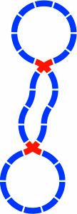
The radius of these circular pieces is the usual 1 quintimeter = 200mm. Below are three examples of layouts using only curved pieces; figure 19-3 is a rough analogue of figure 2-4. Figure 19-4, the flattened version of 19-3, introduces an important crossing.

| 
| 
|
| Figure 19-2 | Figure 19-3 | Figure 19-4 |
|---|
Here is a development from that piece:

| 
| 
|
| Figure 19-5a: The crossing of 19-4 is drawn much larger, the image now including the grooves in which the train wheels roll. | Figure 19-5b: A third segment is added, yielding switches in the lower left and lower right. The piece is drawn in brown because is has both a crossing and a switch. | Figure 19-5c: A third segment is added to 19-5a in a different way. |

| 
| 
|
| Figure 19-5d: A four-segment piece is made by combining all segments of 19-5b and 19-5c. | Figure 19-5e: This astrino [Italian for small star] has has five segments, the maximum for this format. | Figure 19-5f: This pure switch comes from removing three segments from 19-5e. |
| scale 4x | ||
The ability of five curved segments to fit this way is of great convenience to a layout designer.
In a complicated piece such as the astrino, the choice of radius [in this report, usually 200mm to the centerline of the track] greatly influences the arrangement of islands [dark brown] between the grooves [light brown]. For contrast, figure 19-6 contains astrini designed with some other radii:

| 
| 
|
| Figure 19-6a with 150mm radius | Figure 19-6b with 250mm radius | Figure 19-6c with 300mm radius |
| scale 4x | ||
Finding the best radius may be a matter of trial and error, with compromise between conflicting needs. Although the pieces proposed in this report do not attempt to be compatible with track currently on the market, they do maintain a 25mm center-to-center spacing between grooves for compatibility with the rolling stock offered by many vendors. In any case, the present discussion will continue to assume a radius of one quintimeter.
§20. Alpha series. In almost any kind of analysis involving the 36° angle, an important mathematical constant arises. This number is (√5 + 1) ÷ 2, approximately 1.618034, and is frequently symbolized by the uppercase Greek letter Φ. It must not be confused with a closely related constant, (√5 − 1) ÷ 2, approximately 0.618034, which is often written with lowercase Greek φ. Noteworthy is that Φ × φ = Φ − φ = 1. Most expressions that use the smaller phi can be written equally well with the larger, so to minimize confusion in this report the larger phi [1.618034] will be used exclusively.
There are four essential figure eights that can be formed in the 36° system, and they need to be studied because they induce straight segments of inevitable lengths. Two of them will be taken up in this section, and the others in section 21.
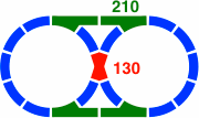
Figure 20-1 contains the first to be examined, with nine curved segments per lobe. Depicted in red as always, the crossing has two straight segments intersecting at an angle that may equally well be regarded as 36° or 144°, and each segment has a length of 130mm [= 400 × tan18°]. Meanwhile, figure 20-2 displays the oval-eight version, each straight segment within a switch having a length of 210mm [= 200 × sec18°].
 | 
|
| Figure 20-1 | Figure 20-2 |
|---|
A second figure eight has seven curved segments per lobe. Because the 551mm [= 400 × tan54°] crossing in figure 20-3a might be impracticably long, figure 20-3b shows an alternate disposition. Both of these crossings involve a 72° [equivalently, 108°] angle.
 | 
|
| Figure 20-3a | Figure 20-3b |
|---|
Figure 20-4 is the added-oval version of figure 20-3. Although the overall layout is symmetric, the implementation is not.
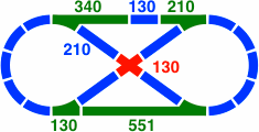 |
| Figure 20-4 |
|---|
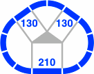
One switch, labeled as 130, has a straight segment of 129.97mm. This distance is close to the minimum of 126.49mm [= √(2202 − 1802)], under the assumption of a 200mm radius and a 40mm track width. A straight segment any shorter would not be able to clear the curved segment, making attachment to other track pieces difficult or impossible. From another point of view, the track width must be no greater than 42.23mm [= 400 × (1 − cos36°) ÷ (1 + cos36°)], or the same problem will occur.
A similar consideration determines that for a 36° crossing piece, as in figure 20-1, the minimum length is 123.11mm [= 40 × (tan54° + sec54°)]. Also, for a 72° crossing piece, as in figure 20-3, the minimum length is 55.06mm [= 40 × (tan18° + sec18°)].
Finally, the minimum angle of curve is 35.10° [= atan(126.49 ÷ 180)], so that this 36° system is just barely possible.
Table 20-A, which is similar in principle to table 4-A, includes the numbers so far derived that are lengths of straight segments. This alpha series shares an important feature with any geometric sequence where the ratio of consecutive terms is Φ: each entry is the sum of the two previous entries [although rounding of these irrational numbers will sometimes obscure that fact].
| Table 20-A: Some values of the alpha series | |||
|---|---|---|---|
| as an integer | to two places | exactly | addends |
| 19 | 18.96 | 400 × tan18° × Φ−4 | 7 + 12 |
| 31 | 30.68 | 400 × tan18° × Φ−3 | 12 + 19 |
| 50 | 49.64 | 400 × tan18° × Φ−2 | 19 + 31 |
| 80 | 80.32 | 400 × tan18° × Φ−1 | 31 + 50 |
| 130 | 129.97 | 400 × tan18° × Φ0 | 50 + 80 |
| 210 | 210.29 | 400 × tan18° × Φ+1 | 80 + 130 |
| 340 | 340.26 | 400 × tan18° × Φ+2 | 130 + 210 |
| 551 | 550.55 | 400 × tan18° × Φ+3 | 210 + 340 |
| 891 | 890.81 | 400 × tan18° × Φ+4 | 340 + 551 |
| α(n) = 400 × tan18° × Φn α(n) = α(n − 1) + α(n − 2) | |||
Practical track lengths from the alpha series will range from 50mm to 340mm.
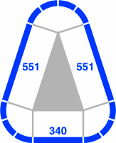
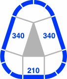
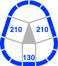
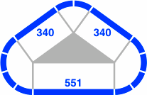
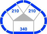
Below are some fundamental triangles the edges of which are in the ratio Φ. These drawings correspond to figure 4-3 in the 45° system. In figure 20-5, the corners of each triangle have 3, 4, and 3 circular segments respectively; in figure 20-6 the numbers of segments are 4, 2, and 4.
 |  | 
|
| Figure 20-5a | Figure 20-5b | Figure 20-5c |
|---|---|---|
 |  | 
|
| Figure 20-6a | Figure 20-6b | Figure 20-6c |
Figure 20-7 shows how a switch like that in the lower left of 20-4 can be combined with its mirror image to make a four-segment piece. An open question is whether there is enough island area to give train wheels sufficient guidance; if so, the piece could substitute for the crossing of 20-1.

|  | 
|
| Figure 20-7a | Figure 20-7b | Figure 20-7c |
|---|---|---|
| scale 4x | ||
As many as five straight segments can feasibly cross at one point, as illustrated in figure 20-8 where the segments have a length of 130mm. The horizontal segment of 20-8c, and either segment of 20-8b, could instead be 80mm.

| 
| 
|
| Figure 20-8a: The 36° crossing of figure 20-1 | Figure 20-8b: The 72° crossing of figure 20-3b | Figure 20-8c: One way to add a third segment |

| 
| 
|
| Figure 20-8d: Another way to add a third segment | Figure 20-8e: Four segments | Figure 20-8f: Five segments |
| scale 4x | ||
The 36° is like the 60° system in that perpendicular crossings of straight segments will not exist.
§21. Beta series. Below are the two remaining figure eights. In figure 21-1 the layout has eight segments in each lobe, while figure 21-2 pictures one with six segments. Unlike the figure eights in the previous section, these offer no way to add an oval in the manner of figure 7-1 or figure 13-2. In this regard, the layouts below correspond to figure 6-3 and figure 14-6.
 | 
|
| Figure 21-1 | Figure 21-2 |
|---|
The distances are found in the beta series of table 21-A, where again each entry is the sum of the two previous.
| Table 21-A: Some values of the beta series | ||||
|---|---|---|---|---|
| as an integer | to two places | exactly | beta series addends | alpha series addends |
| 42 | 42.40 | 400 × tan36° × Φ−4 | 16 + 26 | 12 + 31 |
| 69 | 68.61 | 400 × tan36° × Φ−3 | 26 + 42 | 19 + 50 |
| 111 | 111.01 | 400 × tan36° × Φ−2 | 42 + 69 | 31 + 80 |
| 180 | 179.61 | 400 × tan36° × Φ−1 | 69 + 111 | 50 + 130 |
| 291 | 290.62 | 400 × tan36° × Φ0 | 111 + 180 | 80 + 210 |
| 470 | 470.23 | 400 × tan36° × Φ+1 | 180 + 291 | 130 + 340 |
| 761 | 760.85 | 400 × tan36° × Φ+2 | 291 + 470 | 210 + 551 |
| 1231 | 1231.07 | 400 × tan36° × Φ+3 | 470 + 761 | 340 + 891 |
| 1992 | 1991.92 | 400 × tan36° × Φ+4 | 761 + 1231 | 551 + 1441 |
| β(n) = 400 × tan36° × Φn β(n) = β(n − 1) + β(n − 2) β(n) = α(n + 1) + α(n − 1) β(n) = √5 × α(n) α(n) = β(n − 2) + β(n − 6) + β(n − 10) + β(n − 14) … | ||||
Each beta term is the sum of two next-to-consective alpha terms because Φ−1 + Φ+1 = tan36° ÷ tan18°. As a result, the beta-series values of figures 21-1 and 21-2 can be decomposed into the alpha-series values of figures 21-3 and 21-4. [Note that such a convenient relationship does not exist between the secondary and primary series of the 45° system.] Practical lengths range between 69mm and 291mm.
Although each beta is the combination of two alphas, an alpha does not break down into finitely many betas; thus a practical collection of track will generally use alphas for its straight segments. However, the diagrams on this page will often render a straight region of track as one beta instead of two alphas to reduce pictorial congestion.
Figure 21-3 uses the crossing piece of figure 20-3b, and figure 21-4b uses that of figure 20-1.

|
| Figure 21-3 |
|---|

|
| Figure 21-4a |
|---|

|
| Figure 21-4b |
Although they are not illustrated here, triangles corresponding to figures 20-5 and 20-6 can readily be constructed using straight pieces whose lengths are consecutive values from the beta series.
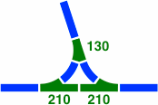
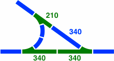
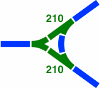
§22. Junctions. Figures 22-1 through 22-3 are some ways in which three tracks might come together in an intersection shaped like a tee or wye.
| 
| 
|
| Figure 22-1 | Figure 22-2 | Figure 22-3 |
|---|
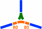
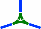
A fourth junction is more complicated. Figure 22-4a shows the first step in its development, where the two ordinary curves are rendered in orange for ease of reference. Next, 22-4b shows the three segments necessary to connect the left and right branches. Because the straight segments are only 80mm [= α(−1)] long, the five orange segments of 22-4a and 22-4b overlap each other, hence they need to be manufactured as one large piece, as in 22-4c. This piece would normally be drawn in green because it is a switch, as in 22-4d. Finally, 22-4e is the same piece drawn at large scale in the manner of figure 19-5f.
 | 
|  | 
|
| Figure 22-4a | Figure 22-4b | Figure 22-4c | Figure 22-4d |
|---|---|---|---|

| |||
| Figure 22-4e scale 4x | |||
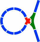
The switch of figure 22-4e is employed in figures 22-5 and 22-6. The former has the crossing of 20-3b, while the latter uses that of 19-4.
 | 
|
| Figure 22-5 | Figure 22-6 |
|---|