
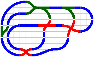
§16. General. A third plan relies upon curved pieces that are one-fourth of a circle. The 90° system so generated turns out to be as easy to use as the 60° system.
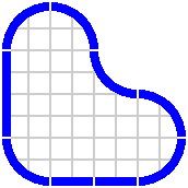
If dimensions are suitably chosen, all pieces will align on an ordinary square grid. For now, grid lines spaced at 100mm [1 decimeter] will suffice, although in section 17 an interval of 50mm [1 semidecimeter] will serve better. Examining the 100mm grid in figure 16-2, one can deduce that the vertical straight piece is 400mm long, while each horizontal is 200mm. Hence there is no need to label straight segments with their length. By similar means one can infer the radii of arcs.
In the examples of figures 16-1 through 16-4, arcs have the usual radius of 1 quintimeter — although in light of the grid spacing, the term bidecimeter is perhaps more pertinent.
|
|
|
| Figure 16-1 | Figure 16-2 |
|---|
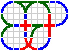
Switches and crossings provide little surprise. Figure 16-4 has a rather shallow gantlet highlighted in yellow on the left-hand side, and on the right-hand side one such gantlet crosses another.
| 
|
| Figure 16-3 | Figure 16-4 |
|---|
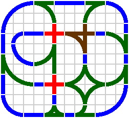
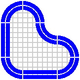
Layouts become more interesting if curves of radius 100mm and 300mm are added.
| 
|
| Figure 16-5 | Figure 16-6 |
|---|
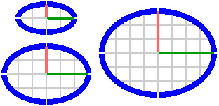
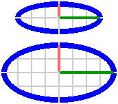
Ellipses are manageable in the 90° system. In figure 16-7a, the difference between major radius [rendered in green] and minor [salmon] is 100mm; in figure 16-7b, the difference is 200mm.
| 
|
| Figure 16-7a | Figure 16-7b |
|---|
Figure 16-8 is derived from figure 16-6 by removing many of the circular arcs and replacing them with noncirculars.
 |
| Figure 16-8 |
|---|
Figure 16-9 shows several sizes of ess curves; each is made of two equal circular arcs. For each arc are given its radius and the angle through which it passes.
 |  | 
|  |  | 
| |
| Width | 100mm | 100mm | 100mm | 200mm | 200mm | 200mm |
|---|---|---|---|---|---|---|
| Length | 200mm | 300mm | 400mm | 200mm | 300mm | 400mm |
| Radius | 125mm | 250mm | 425mm | 100mm | 162.5mm | 250mm |
| Angle | 53.13° | 36.87° | 28.07° | 90.00° | 67.38° | 53.13° |
| Figure | 16-9a | 16-9b | 16-9c | 16-9d | 16-9e | 16-9f |
Figure 16-10 shows ess curves in various uses, including crossings and switches.
 |
| Figure 16-10 |
|---|
Ess curves in fact need not be composed of circular arcs; a sine curve and a cubic polynomial, for example, are two of many other possibilities.
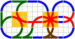
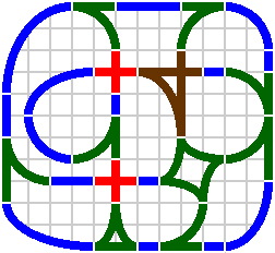
Figure 16-11a reveals how the gantlet of figure 16-4 can be modified into a double switch similar to that of figure 9-4. Instead of using a curve of radius 200mm, a smaller radius of 170.71mm [= 100 + 50 × √2] is employed. Straight portions, rendered in pink, of length 29.29mm [= 200 − 170.71] fill what would otherwise be gaps at the edge. Figure 16-11b shows two of these switches crossing each other, this time drawn in brown because the combination qualifies as both a crossing and a switch.

| 
|
| Figure 16-11a | Figure 16-11b |
|---|
§17. Double tracking. An elementary yet satisfactory approach is to use curves whose radii are multiples of 50mm, and straight pieces whose lengths are multiples of 50mm. Consequently, the illustrations below employ a 50mm grid.
Figure 17-1 does not use any special pieces to achieve double tracking; rather it has ordinary [single-track] pieces lying 10mm apart. Curves are of radii 200mm and 250mm.
 |
| Figure 17-1 |
|---|
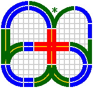
Practically all crossings will have to be implemented as double-track pieces, as will many switches; in figure 17-2 they can be identified by their yellow medians.
 |
| Figure 17-2 |
|---|
The asterisked switch in figure 17-2 has two nonconcentric arcs of different radius. Although its production should pose no great technical problem, demand for so specialized a piece would likely be weak, and there is doubt whether a business would find it profitable to deal in. The increasing computerization of manufacturing equipment may resolve the issue: short-run orders are becoming ever more feasible.
There does not appear to be any technical problem with triple tracking, quadruple, et cetera.
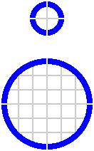
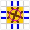
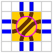
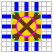
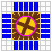
§18. Turntables. Figure 18-1 shows, on a 100mm grid, the most elementary turntable in the 90° system; but this gives only a glimpse into the range of possibilities.
 |
| Figure 18-1 |
|---|
It is feasible for the ring to have two entrances per side, and for the disk to have multiple segments with crossings or switches.
| 
| 
|
| Figure 18-2a | Figure 18-2b | Figure 18-2c |
|---|
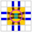
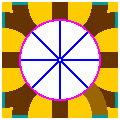
Figure 18-3 facilitates a detailed look at the geometry of one possible configuration.
| 
| 
|
| Figure 18-3a | Figure 18-3b scale 2x | Figure 18-3c scale 2x |
With these numbers, each track is perpendicular to the disk-ring boundary [pink circle] where it meets that boundary, averting the sharp-corner problem of figure 15-7d. Also, figure 18-3c discloses a consistent 45° spacing of the inner portals, analogous to the 30° angle of figure 15-8c.
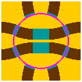
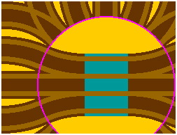
On a 50mm grid, another turntable naturally arises as pictured in figure 18-4. Although it can use the same disks as the turntable of figure 18-3, this ring differs from the former by having switches — hence outer portals [12] outnumber inner [8]. Although each arc on the ring does extend all the way to its inner portal, it is connected to its outer portal by a straight portion [in teal] of length 6.57mm [= 50 − 100 × √2 + 97.99]. As before, inner portals are evenly spaced at 45°.The curves on this ring have a radius of 104.85mm [= (100 × √2 − 97.99) ÷ tan22.5°] and an angle of 45°. One instance of this arc is rendered in light brown, rather than dark, at the bottom right corner of figure 18-4b.
| 
|
| Figure 18-4a | Figure 18-4b scale 2x |
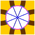
With no change in dimensions, the two preceding rings can be combined, yielding an elaborate turntable with 20 outer and 16 inner portals [figure 18-5]. The angular spacing of inner portals becomes 22.5°.
| 
|
| Figure 18-5a | Figure 18-5b scale 2x |
To the disk of figure 18-3b can be added a third, straight, segment in the middle creating a gantlet, but the scale of 2x in figure 18-5c is not adequate to make the design clear.

| 
|
| Figure 18-5c scale 2x | Figure 18-5d detail of figure 18-5c scale 5x |
The visibility problem is addressed by figure 18-5d. Besides being scaled at 5x, this latter figure depicts in light brown the grooves in which train wheels will roll. The assumed track specifications are the same as in the train car page: the grooves are 7mm wide, between them is a median of 18mm, and all these reside between two curbs of width 4mm — thus overall track width remains the familiar 40mm. Noteworthy is that the center-to-center distance between the grooves is 25mm. At the heart of the gantlet [teal], three parallel straight segments share four grooves in an ambijugal relationship.