Track connectors.
Version of Tuesday 5 May 2012.
This page discusses the means by which the end of one track piece is attached to the next. The illustrations happen to use the 60° system, but the comments apply to systems of any other angle.
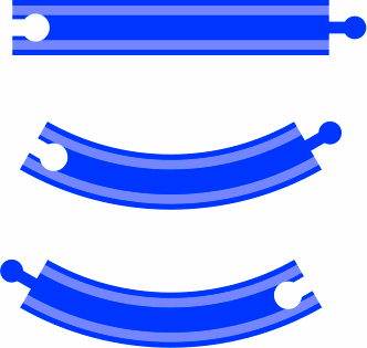
To display the track connectors clearly requires a considerably larger scale than that on the main pages [for example the 45° system]. As a result, some figures [among them 1-1] are at six times the normal scale; they include a depiction of the grooves in which train wheels roll. The other figures [for instance 1-2] are at three times normal scale, and do not show the grooves. Although the pictures are large, they are mainly blank and hence compress into small files.
§1. For wooden toy train track, by far the most popular choice has been to have a female connector on one end of a track segment and a male on the other [called a mixed segment], as shown in figure 1-1. On asymmetric pieces, manufacturers usually cut grooves on both sides of the material, allowing the track to be flipped over for a different usage; then the two mirror-image curves in 1-1 will be opposite sides of the same item. Such grooving of both sides helps reduce the catalog of possible pieces.
 |
| Figure 1-1 |
|---|
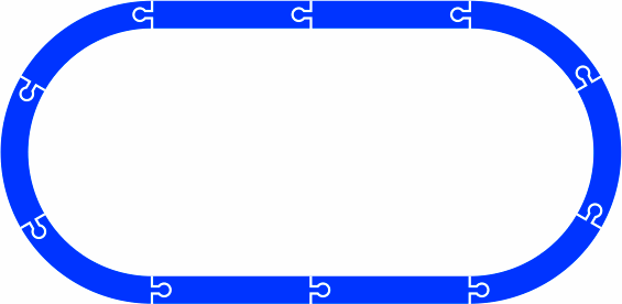
For simple layouts, such as figure 1-2, such a scheme is sufficient.
 |
| Figure 1-2 |
|---|
Figure 1-3 includes a 60° crossing, with all segments mixed.
 |
| Figure 1-3 |
|---|
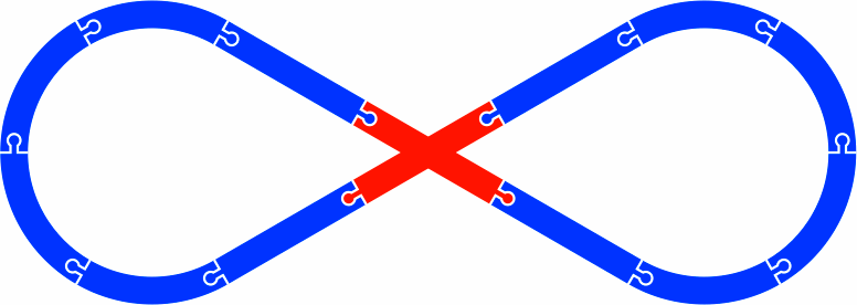
Figure 1-4 also includes a 60° crossing with all segments mixed. Still, this crossing differs from the previous, because in 1-3 the angle between male connectors is 60°, but in 1-4 that angle is 120°.
 |
| Figure 1-4 |
|---|
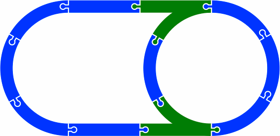
In figure 1-5 each segment is mixed, but the two switches are of opposite gender.
 |
| Figure 1-5 |
|---|
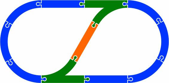
Figure 1-6 is among the simplest layouts that require an unmixed segment, here shown in orange.
 |
| Figure 1-6 |
|---|
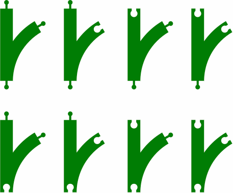
Figure 1-7 reveals that an asymmetric two-segment switch can have any of eight arrangements of male and female connectors. It gives a glimpse into the inconveniently large number of possible pieces in the traditional connector system.
 |
| Figure 1-7 |
|---|
In the three-segment switch of figure 1-8, at least one segment will assuredly be unmixed.
 |
| Figure 1-8 |
|---|
Figure 1-9a is part of a layout where two female segments happen to meet. A dogbone-shaped adapter [in orange] takes care of the problem.
 |
| Figure 1-9a |
|---|
If two segments need to meet end-to-end but both are male, as in figure 1-9b, the problem is more difficult, as an adapter [in orange] adds some length to the layout; the minimum feasible length is about 50mm. Adjustments elsewhere in the layout will be necessary.
 |
| Figure 1-9b |
|---|
A few train sets offer track with female connectors on both ends of all segments, and include a supply of dogbone connectors. This approach greatly simplifies both the manufacturer's catalog and the hobbyist's layout design. A risk, however, is that younger children will try to eat the dogbones.
§2. Figure 2-1 displays a different kind of connector, this based on a dovetail. The advantage over the traditional method discussed above is that either end of any segment will attach to either end of any other segment without any concerns of gender, and no small parts such as dogbones are required. The drawback is that pieces, when turned upside down, will not fit at all.
A response to this lack of fit is is to have two narrow grooves on one side of each piece for trains, as in the top of figure 2-1. On the other side will be one wide groove serving as a road for automobiles, as in the middle image. The bottom part of 2-1 shows how an attempt to attach track to road will fail, preventing any connection with inconsistent grooves.
 |
| Figure 2-1 |
|---|
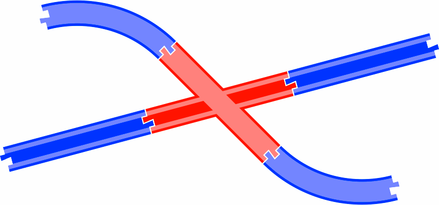
Figure 2-2 shows what a crossing of road and track might look like.
 |
| Figure 2-2 |
|---|
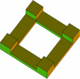
§3. A third method always allows either end of one segment to be attached to either end of another segment, even when one of them is flipped over. The connector, which readily generalizes into a pillar for elevated tracks and roads, is much larger than the dogbone above thus reducing the risk of juvenile ingestion.
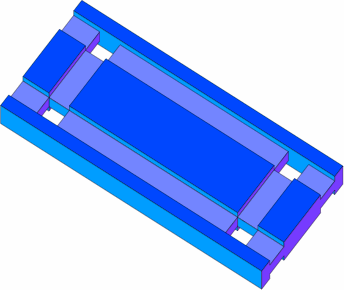
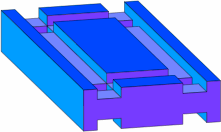
Although the pieces are easy to use, to explain their design requires images more detailed than those above, so the more pictorial axonometric projections are employed. Figure 3-1 offers two views of a track that reflects the usual track dimensions and a connector:
 | 
|
 | 
|
| Figure 3-1 | |
|---|---|
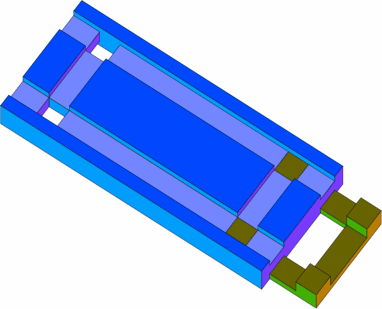
The connector fits the track as in figure 3-2 below. The bottom of the connector is flush with the bottom of the track, both resting directly on the tabletop. Meanwhile, the top of the peg is flush with the floor of the groove for smooth rolling of train wheels.
|
| Figure 3-2 |
|---|
The track has square holes into which the connector's square pegs fit, but the manufacturer might choose some other size, shape, or spacing for the pegs and holes; the squares used here are merely a convenient example.
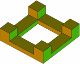
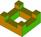
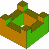
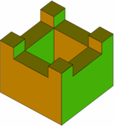
Pillars can be of any height, a few of them shown in figure 3-3. The pillar of minimum height is the same as the connector of figure 3-1.
 | 
|  | 
|
| Figure 3-3 | |||
|---|---|---|---|
The variety of possible pillar heights allows a gently sloping incline to be constructed, but nothing about this system prevents the use of specialized ramp pieces instead.
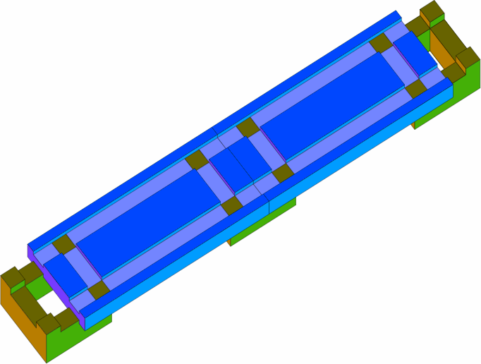
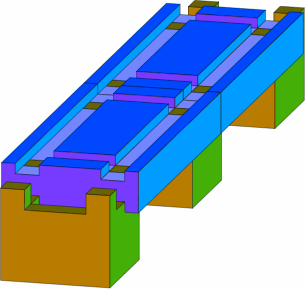
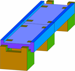
Figure 3-4 contains several views of an elevated track, with a road substituted for track in the image at the lower right.
| |

| |
 | 
|
| Figure 3-4 | |
|---|---|
Although they are not shown, pieces that have track on one side and road on the other are easily manufactured.
One limitation of this pillar scheme is that an elevated track cannot constructed over a parallel track beneath. On the other hand, these pillars can easily elevate suitably-designed turntables and double track, in part because the pillars are no wider than the track.